9-5
9.3 Handling Index Registers
9.3.1 Index Registers
• Like other registers, index registers have 14 points, I0 to ID, for reading and writing 16-bit data.
• Use an index register to indirectly specify a memory area number. (This is also called index
modification.)
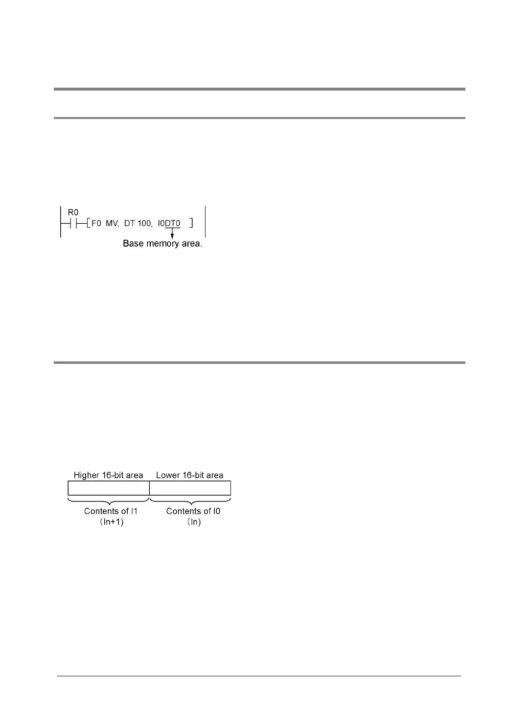
<Example>
Transferring the contents of data register DT100 to the number specified by the contents of an
index register.
In this example, the number of the destination data register varies depending on the contents of I0 with
DT0 acting as a base. For example, when I0 contains K10, the destination will be DT10, and when I0 is
K20, the destination will be DT20.
• In this way, index registers allow the specification of multiple memory areas with a single instruction,
and thus index registers are very convenient when handling large amounts of data.
9.3.2 Memory Areas Which can be Modified with Index Registers
• Index registers can be used to modify other types of memory areas in addition to data registers DT.
<Example> I0WX0, I0WY1, I0WR0, I0SV0, I0EV2, I0DT100
• Constants can also be modified.
<Example> I0K10, I0H1001
• An index register cannot modify another index register.
<Example> I0I0, I0I1
• When using index modification with an instruction which handles 32-bit data, specify with I0. In this
case, I0 and I1 are handled together as 32-bit data.