6-4
6.2 Function Specifications and Restricted Items
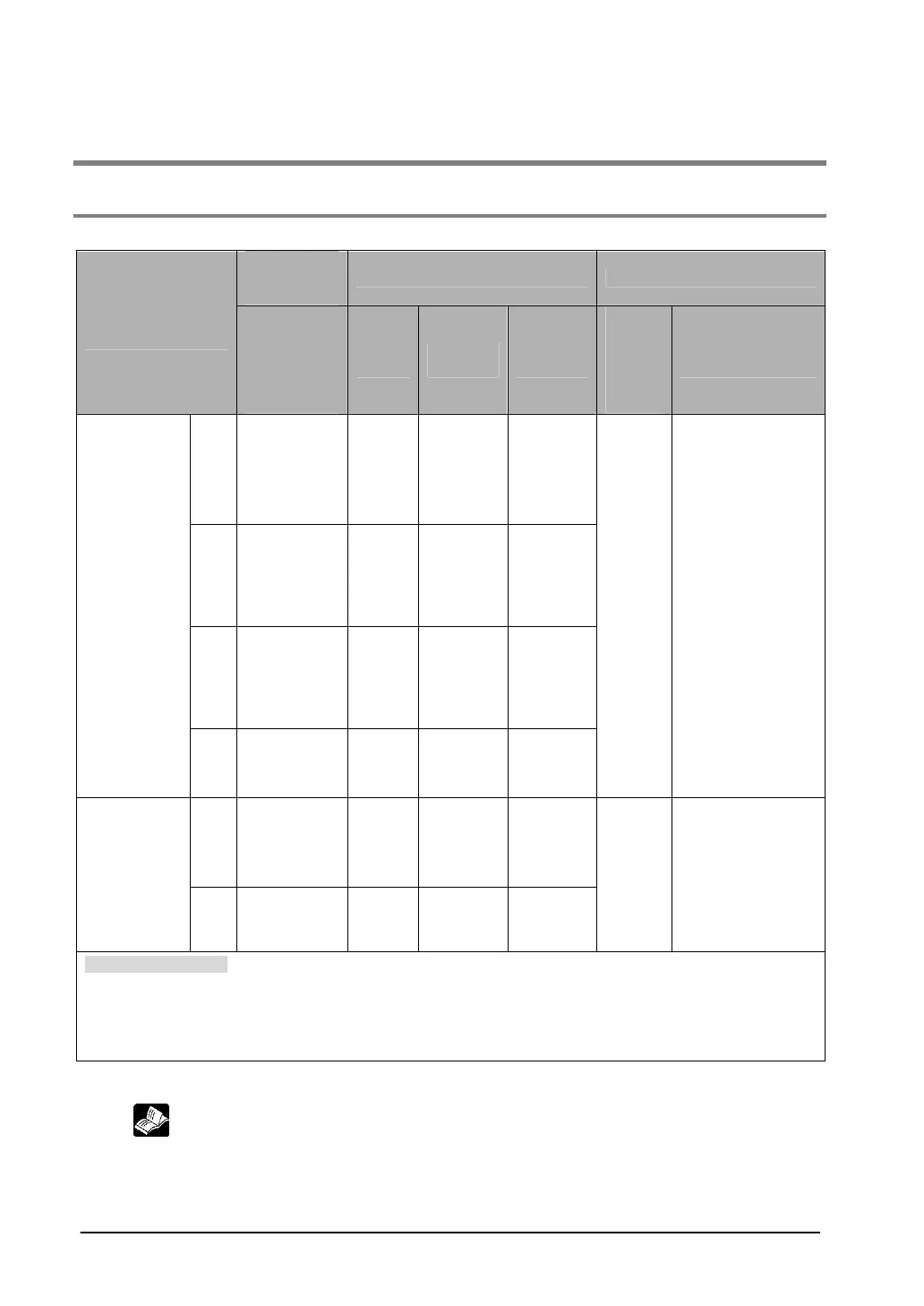
6.2.1 Specifications
High-speed counter function
Input/output
contact No.
being used
Memory area being used Performance specifications
High-speed counter
channel No.
Input contact
number
(value in
parenthesis
is reset
input)
Note1)
Control
flag
Elapsed
value area
Target
value area
Mini-
mum
input
pulse
width
Note2)
Maximu←m
counting speed
CH0
X0
(X2)
R903A
DT90044
to
DT90045
DT90046
to
DT90047
CH1
X1
(X2)
R903B
DT90048
to
DT90049
DT90050
to
DT90051
CH2
X3
(X5)
R903C
DT90200
to
DT90201
DT90202
to
DT90203
[Single phase]
Incre-mental,
Decre-mental
CH3
X4
(X5)
R903D
DT90204
to
DT90205
DT90206
to
DT90207
10µs
(100µs)
Using 1 channel:
Max. 50kHz (x1-ch)
Using 2 channels:
Max. 30kHz (x2-ch)
Using 3 channels:
Max. 20kHz (x3-ch)
Using 4 channels:
Max. 20kHz (x4-ch)
CH0
X0
X1
(X2)
R903A
DT90044
to
DT90045
DT90046
to
DT90047
[2-phase]
2-phase input
One input,
Direction
distinction
CH2
X3
X4
(X5)
R903C
DT90200
to
DT90201
DT90202
to
DT90203
25µs
(100µs)
Using 1 channel:
Max. 20kHz (x1-ch)
Using 2 channels:
Max. 15kHz (x2-ch)
Related instructions:
F0(MV) :High-speed counter control
F1(DMV) :Read/write of elapsed value of high-speed counter
F166(HC1S) :Target value match on (Specify the desired output from Y0 to Y7 using instruction)
F167(CH1R) :Target value match off (Specify the desired output from Y0 to Y7 using instruction)
Note1) Reset input X2 can be set to either CH0 or CH1. Reset input X5 can be set to either CH2 or
CH3.
Note2) Reference: For information on minimum input pulse width,
see <6.3.3 Minimum Input Pulse Width>.