3-9
3.4.2 FPΣ Expansion Data Memory Unit
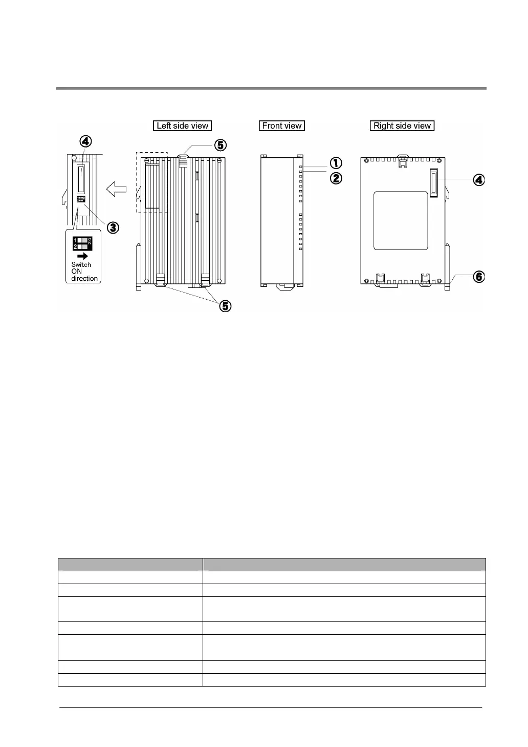
Parts and Functions
① POWER LED (Green)
② BATT LED (Red)
Lights out: Battery voltage is normal.
Lights on: The voltage of the battery for memory backup reduced,
or the memory backup SW is turned off.
③ Memory backup SW
The factory default setting is “OFF” so turn both SW1 and 2 “ON” when using the unit. If this SW is
turned off, the memory backup is not available as the memory is separated from the built-in battery. Turn
it on when the unit is used.
④ Connector for FPΣ expansion
This connector is used to expand the unit for FPΣ.
⑤ Expansion hook
This hook is used to secure expansion units. The hook is also used for installation on flat type mounting
plate (AFP0804).
⑥ DIN hook
The unit enables attachment at a touch to a DIN rail. The lever is also used for installation on slim 30
type mounting plate (AFP0811).
General specifications
Item Description
Ambient temperature/humidity 0 to +55 °C, 30 to 85 %RH (at 25°C, non-condensing)
Storage temperature/humidity -20 to +70 °C, 30 to 85 %RH (at 25°C, non-condensing)
Vibration resistance
10 to 55 Hz, 1 cycle/min, double amplitude of 0.75 mm,
10 min on 3 axes
Shock resistance Shock of 98 m/s
2
, 4 times on 3 axes
Noise immunity
1000 Vp-p with pulse widths 50 ns and 1µs
(based on in-house measurements
Operation condition Free from corrosive gases and excessive dust
Weight Approx. 80 g