6-59
6.5 PWM Output Function
6.5.1 Overview
PWM output function
With the F173 (PWMH) instruction, the pulse width modulation output of the specified duty ratio is
obtained.
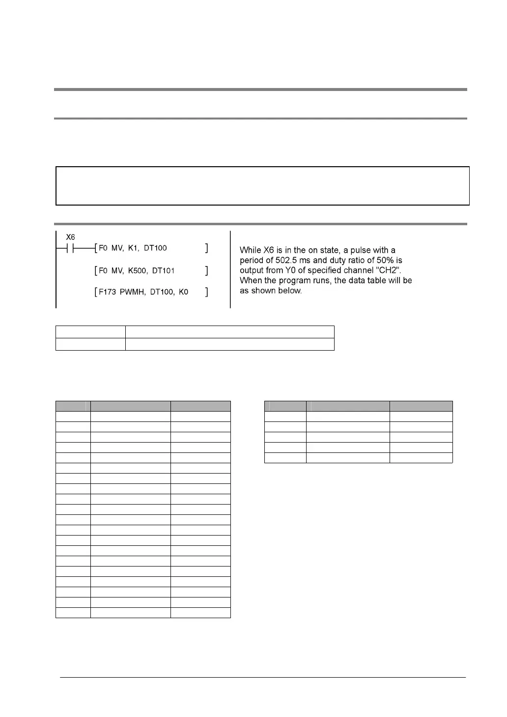
System register setting
When using the PWM output function, set the channel CH0 and CH2 with system registers 400 and 401
to “High-speed counter not used”.
6.5.2 PWM Output Instruction F173
Data table
DT100 Control code *1 : K1
DT101 Duty *2 : 50%
*1: Specify the control code by setting the K constant.
Resolution of 1000 Resolution of 100
K Frequency (Hz) Period (ms) K Frequency (Hz) Period (ms)
K0 1.5 666.67 K20 15.6 k 0.06
K1 2.0 502.51 K21 20.8 k 0.05
K2 4.1 245.70 K22 25.0 k 0.04
K3 6.1 163.93 K23 31.3 k 0.03
K4 8.1 122.85 K24 41.7 k 0.02
K5 9.8 102.35
K6 19.5 51.20
K7 48.8 20.48
K8 97.7 10.24
K9 201.6 4.96
K10 403.2 2.48
K11 500.0 2.00
K12 694.4 1.44
K13 1.0 k 0.96
K14 1.3 k 0.80
K15 1.6 k 0.64
K16 2.1 k 0.48
K17 3.1 k 0.32
K18 6.3 k 0.16
K19 12.5 k 0.08