7-74
7.6.4 Connection Example of PC(PLC) link
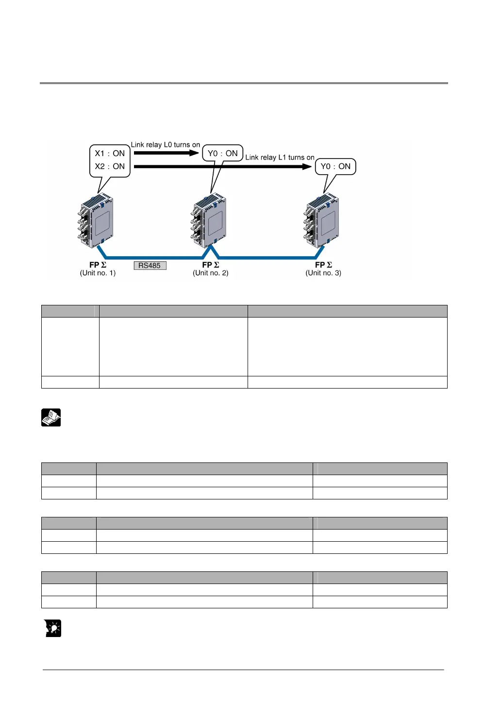
When using three PLCs
The following example demonstrates how the PLC can be connected to two other FPΣ PLCs using a
PC(PLC) link connection. In the example shown here, link relays are use. When X1 of control unit no. 1
turns on, Y1 of unit no. 2 turns on. When X2 of unit no. 1 turns on, Y1 of unit no. 3 turns on.
System register settings
When using a PC(PLC) link, the communication format and baud rate are fixed.
No. Name Set Value
No. 413 Communication format for COM1
port
Data length: ……
Parity check: …..
Stop bit: …………
Terminator: ……..
Header: …………
8 bits
Odd
1 bit
CR
No STX
No. 415 Baud rate setting for COM1 port 115200 bps
Note) The baud rate of the AFPG806 must be identically set to 115200 bps by the system register and
the dip switch located in the communication cassette.
Reference: <7.1.4 Setting of AFPG806 Switch>.
Unit no. and communication mode settings
- Setting for unit no. 1
No. Name Set value
No. 410 COM1 port unit no. 1
No. 412 COM1 port selection of communication mode PC(PLC) link
- Setting for unit no. 2
No. Name Set value
No. 410 COM1 port unit no. 2
No. 412 COM1 port selection of communication mode PC(PLC) link
- Setting for unit no. 3
No. Name Set value
No. 410 COM1 port unit no. 3
No. 412 COM1 port selection of communication mode PC(PLC) link
Key Point:
Make sure the same unit number is not used for more than one of the PLCs connected through the
PC(PLC) link function.