7-75
Link area allocation
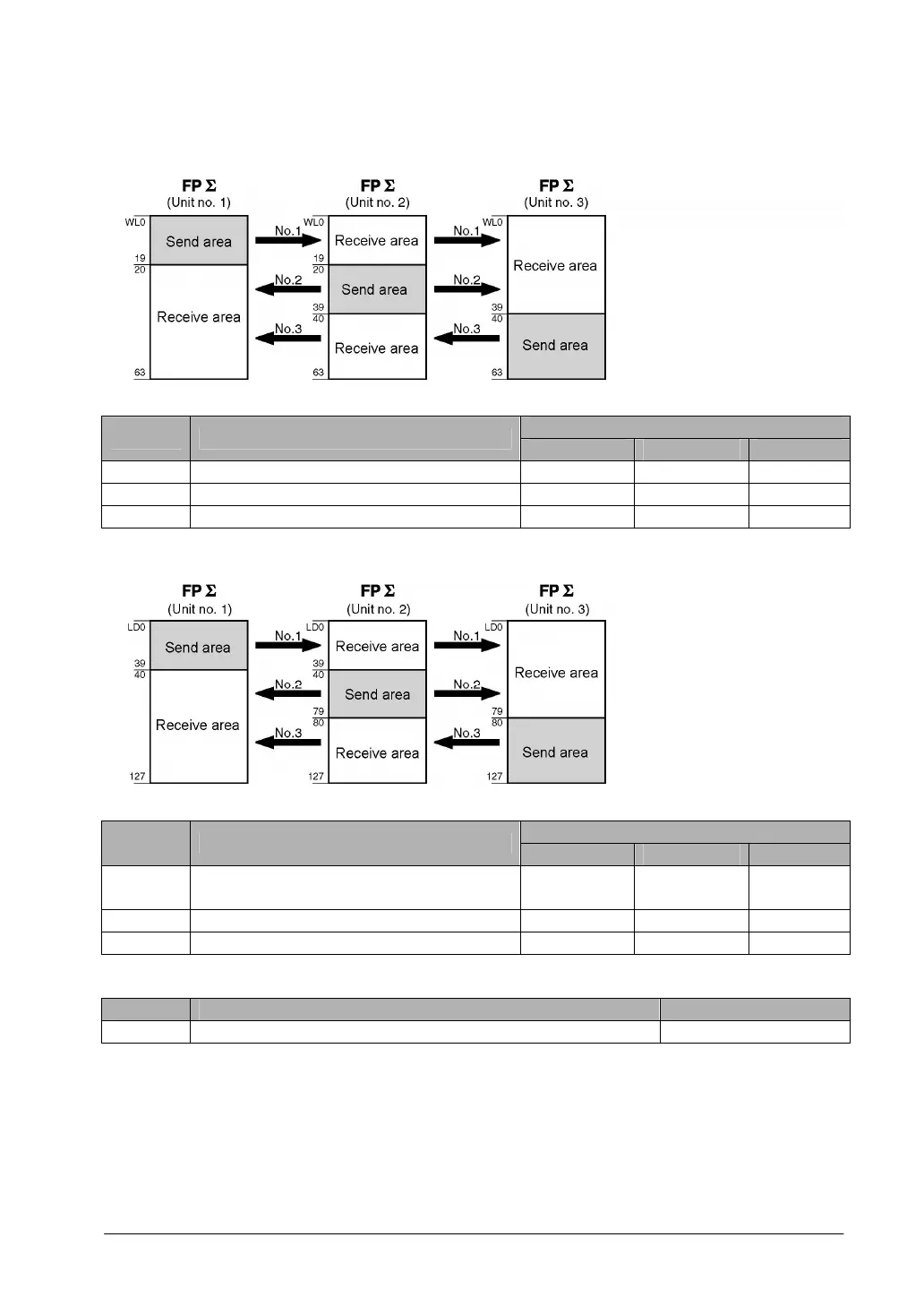
- Link relay allocation
System registers
Set value of various control units
No. Name
No. 1 No. 2 No. 3
No. 40 Range of link relays used for PC(PLC) link 64 64 64
No. 42 Start address of link relay send area 0 20 40
No. 43 Size of link relay send area 20 20 24
- Link register allocation
System registers
Set value of various control units
No. Name
No. 1 No. 2 No. 3
No. 41 Range of link registers used for PC(PLC)
link
128 128 128
No. 44 Start address of link register send area 0 40 80
No. 45 Size of link register send area 40 40 48
Setting the largest unit number
No. Name Set value
No. 47 Largest unit number setting for PC(PLC) link 3