6-53
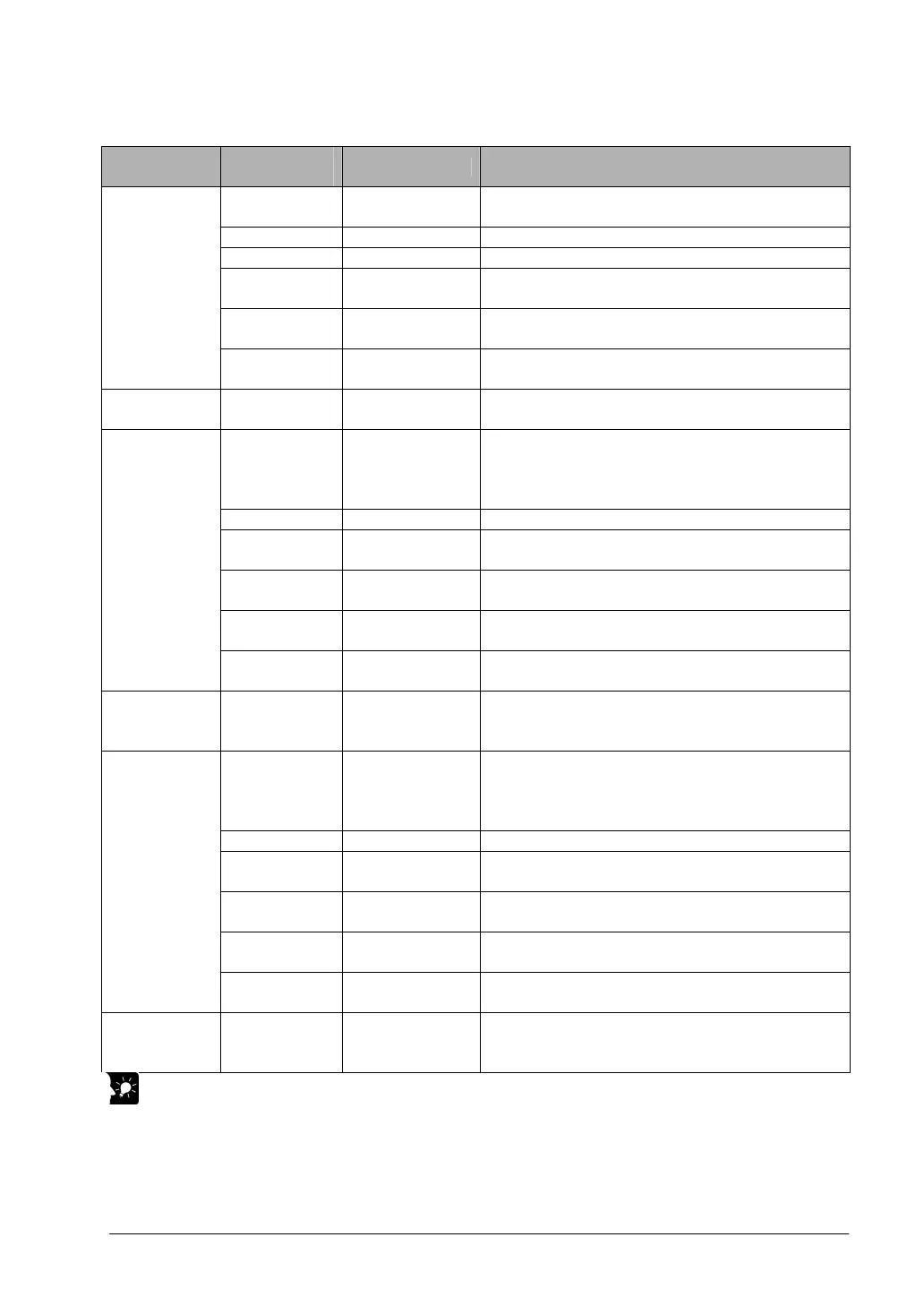
Data register allocation
Item
Data register
No.
Details On this program details
DT0 to DT1 Control code
Control code when executing linear interpolation,
absolute
DT2 to DT3 Startup speed 2000 Hz
DT4 to DT5 Target speed 2000 Hz
DT6
Acceleration/de-
celeration time
0 ms
DT8 to DT9
Target position
(X-axis)
Specify the target position of X-axis when moving from
P1 to P2 and P3 to P4.
User setting
area for linear
interpolation
P1 to P2
P3 to P4
DT10 to DT11
Target position
(Y-axis)
Specify the target position of Y-axis when moving from
P1 to P2 and P3 to P4.
Work area DT12 to DT23
Operation result
storage area
Parameters calculated due to instruction execution are
stored.
DT40 to DT41 Control code
Specify control codes when executing the circular
interpolation of P4 to P1.
Stop mode, Pass position setting, Absolute
From CH0-CW to CH2-CW direction
DT42 to DT43 Composite speed 2000 Hz
DT44 to DT45
Target position
(X-axis)
Specify the target position of X-axis when moving from
P4 to P1.
DT46 to DT47
Target position
(Y-axis)
Specify the target position of Y-axis when moving from
P4 to P1.
DT48 to DT49
Pass position
(X-axis)
Specify the X-coodinate of the pass position when
moving from P4 to P1.
User setting
are for circular
interpolation
P4 to P1
DT50 to DT51
Pass position
(Y-axis)
Specify the Y-coodinate of the pass position when
moving from P4 to P1.
Work area for
circular
interpolation
DT52 to DT57
Operation result
storage area
Parameters calculated due to instruction execution are
stored.
DT60 to DT61 Control code
Specify control codes when executing the circular
interpolation of P2 to P3.
Stop mode, Center position setting, Absolute
From CH0-CW to CH2-CW direction
DT62 to DT63 Composite speed 2000 Hz
DT64 to DT65
Target position
(X-axis)
Specify the target position of X-axis when moving from
P2 to P3.
DT66 to DT67
Target position
(Y-axis)
Specify the target position of Y-axis when moving from
P2 to P3.
DT68 to DT69
Center position
(X-axis)
Specify the X-coodinate of the center position when
executing the circular interpolation of P2 to P3.
User setting
area for
circular
interpolation
P2 to P3
DT70 to DT71
Center position
(Y-axis)
Specify the Y-coodinate of the center position when
executing the circular interpolation of P2 to P3.
Work area for
circular
interpolation
DT72 to DT73
Operation result
storage area
Parameters calculated due to instruction execution are
stored.
Key Point:
• With this program, because the next action that follows circular interpolation control is linear
interpolation, the control code is designated with the stop mode.
• The rotation direction during circular interpolation is the same direction for both P2 to P3 and P4 to P1.
Designate the control code rotation direction with “from CH0-CW direction to CH2-CW direction”.
• Use the circular interpolation control flag R904E to verify completion of the circular interpolation action.