7-68
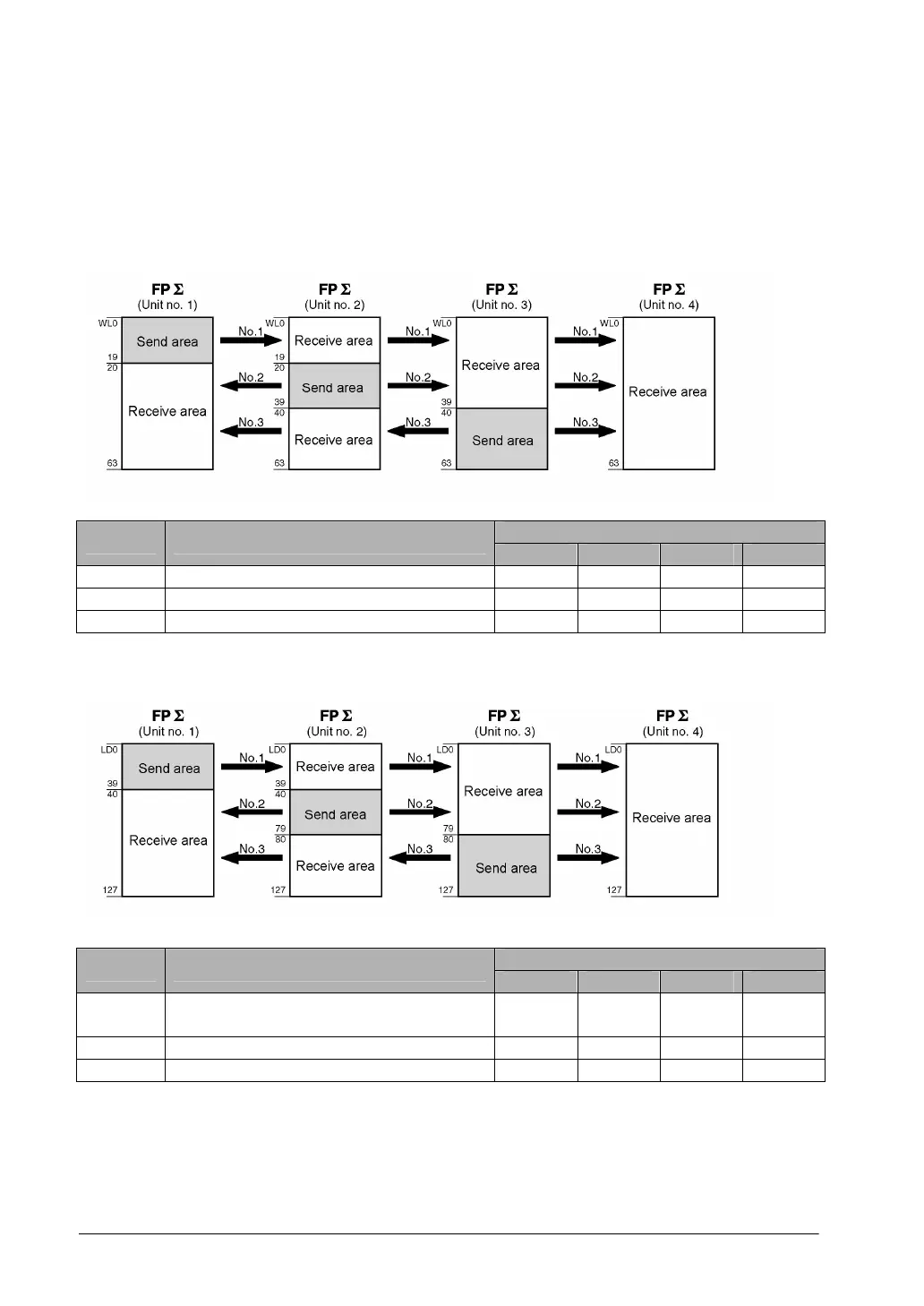
[Example]
The PC(PLC) link areas are divided into send and receive areas. The link relays and link registers are
transmitted from the send area to the receive area of a different FPΣ. The link relays and registers in the
receive area on the receiving side must be within the same area as on the sending side.
For PC(PLC) link 0
Link relay allocation
System registers
Set value of various control units
No. Name
No. 1 No. 2 No. 3 No. 4
No. 40 Range of link relays used for PC(PLC) link 64 64 64 64
No. 42 Start address of link relay send area 0 20 40 0
No. 43 Size of link relay send area 20 20 24 0
Note) No. 40 (range of link relays) must be set to the same range for all the units.
System register allocation
System registers
Set value of various control units
No. Name
No. 1 No. 2 No. 3 No. 4
No. 41 Range of link registers used for PC(PLC)
link
128 128 128 128
No. 44 Start address of link register send area 0 40 80 0
No. 45 Size of link register send area 40 40 48 0
Note) No. 41 (range of link registers) must be set to the same range for all the units.
When link areas are allocated as shown above, the send area of unit no. 1 can be transmitted to the
receive areas of units no. 2, 3 and 4. Also, the receive area of unit no. 1 can receive data from the send
areas of units no. 2 and 3 . Unit no. 4 is allocated as a receive area only and can receive data from units
no. 1, 2 and 3, but cannot send data to other units.