10-9
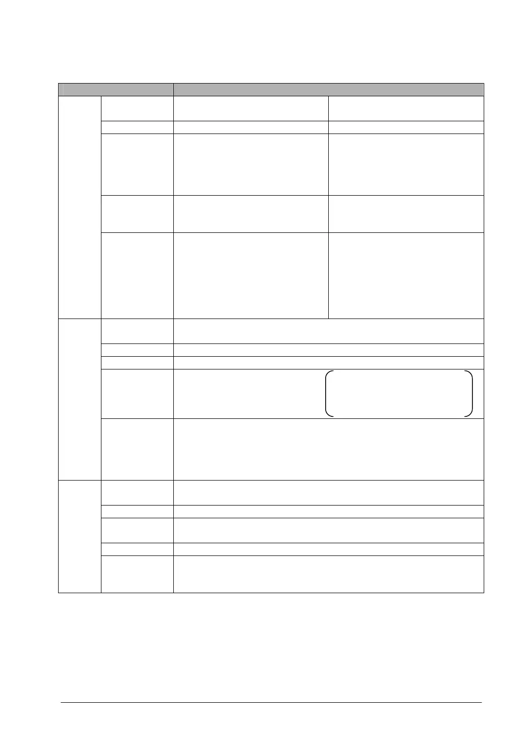
High-speed counter, pulse output and PWM output specifications
Item Descriptions
No. of input
points
When using single-phase: Max. 4
channels
When using 2-phase: Max. 2
channels
Used ch.
Note2)
ch0 to ch4 ch0, ch2
Max. counting
speed
When using single-phase:
for 1 channel: Max. 50kHz (x1ch)
for 2 channels: Max. 30kHz (x2ch)
for 3 or 4 channels: Max. 20kHz (x3
to 4ch)
When using 2-phase:
for 1 channel: Max. 20kHz (x1ch)
for 2 channels: Max. 15kHz (x2ch)
Input mode
When using single-phase:
Addition input,
Subtraction input
When using 2-phase:
Two-phase input, One input,
Direction distinction input
High
speed
coun-
ter
Input contact
used
Note1)
When using single-phase:
X0: count input (ch0)
X1: count input (ch1)
X2: reset input (ch0, ch1)
X3: count input (ch2)
X4: count input (ch3)
X5: reset input (ch2, ch3)
When using 2-phase:
X0, X1: count input (ch0)
X2: reset input (ch0)
X3, X4: count input (ch2)
X5: reset input (ch2)
No. of output
points
Max. 2 channels
Used ch
Note2)
ch0, ch2
Output mode CW and CCW mode, Pulse and Sign mode
Max. output
frequency
When using 1 channel: Max.
100kHZ (x1ch)
When using 2 channels: Max.
60kHz (x2ch)
When using linear interpolation
function: Max. 100kHz
When using circular interpolation
function: Max. 20kHz
Pulse
output
Input/output
contact used
Note1)
<ch0>
X2: Home input
Y0: CW output (Pulse output)
Y1: CCW output (Sign output)
Y2: Deviation counter reset output
<ch2>
X5: Home input
Y3: CW output (Pulse output)
Y4: CCW output (Sign output)
Y5: Deviation counter reset output
No. of output
points
Max. 2 channels
Used ch
Note2)
ch0, ch2
Output
frequency
1.5 to 12.5kHz (at resolution of 1000), 15.6 to 41.7kHZ
(at resolution of 100)
Output duty 0.0 to 99.9% (at resolution of 1000), 1 to 99% (at reslution of 100)
PWM
output
Output
contact used
Note1)
<ch0>Y0, <ch2>Y3
Note1)The contacts noted above cannot be allocated for more than one function. Also, contacts that are
not assigned to the various functions can be used as general inputs/outputs. Inputs functions can
be used as general inputs/outputs. Inputs X0 to X5 are pulse catch inputs, and can also be used
for interrupt input.
Note2)The pulse output, PWM output and high-speed counter of the same channel cannot be used at
the same time.