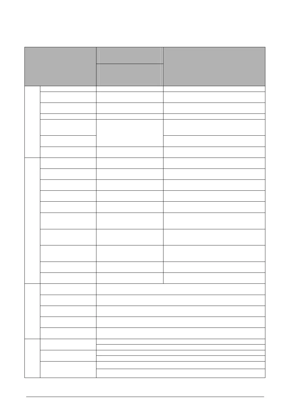
10-16
FPΣ 32k type
Number of points and
range of memory area
available for use
Item
C32TH/C32THTM
C32T2H/C32T2HTM
C24R2H/C24R2HTM
C28P2H/C28P2HTM
Function
External input
Note1)
(X) 1184 points (X0 to X73F) Turns on or off based on external input.
External output
Note1)
(Y)
1184 points (Y0 to Y73F) Externally outputs on or off state
Internal relay
Note2)
(R) 4096 points (R0 to R255F)
Relay which turns on or off only within
program.
Link relay
Note2)
(L) 2048 points (L0 to R127F) This relay is a shared relay used for PLC link.
Timer
Note2)
(T)
This goes on when the timer reaches the
specified time. It corresponds to the timer
number.
Counter
Note2)
(C)
1024 points (T0 to
T1007/C1008 to C1023)
Note3)
This goes on when the timer increments. It
corresponds to the timer number.
Relay
Special internal relay
(R)
176 points (R9000 to R910F)
Relay which turns on or off based on specific
conditions and is used as a flag.
External input
Note1)
(WX)
74 words (WX0 to WX73)
Code for speciyfying 16 external input points
as one word (16 bits) of data.
External output
Note1)
(WY)
74 words (WY0 to WY73)
Code for specifying 16 external output points
as one word (16 bits) of data.
Internal relay
Note2)
(WR)
256 words (WR0 to WR255)
Code for specifying 16 internal relay points as
one word (16 bits) of data.
Link relay (WL) 128 words (WL0 to WL127)
Code for specifying 16 link relay points as one
word (16 bits) of data.
Data register
Note2)
(DT)
32765 words (DT0 to
DT32764)
Data memory used in program. Data is
handled in 16-bit units (one word).
Link register
Note2)
(LD) 256 words (LD0 to LD255)
This is a shared data memory which is used
within the PLC link. Data is handled in 16-bit
units (one word).
Timer/Counter set
value area
Note2)
(SV)
1024 words (SV0 to SV1023)
Data memory for storing a target value of a
timer and setting value of a counter. Stores by
timer/counter number
Timer/Couner elapsed
value area
Note2)
(EV)
1024 words (EV0 to EV1023)
Data memory for storing the elapsed value
during operation of a timer/counter. Stores by
timer/counter number.
Special data register
(DT)
260 words (DT90000 to
DT90259)
Data memory for storing specific data. Various
settings and error codes are stored.
Memory area
Index register (I) 14 words (I0 to ID)
Register can be used as an address of
memory area and constants modifier.
Master control relay
points (MCR)
256
Number of labels
(JP and LOOP)
256
Number of step
ladders
1000 stages
Number of
subroutines
100 subroutines
Control
Instruction point
Number of interrupt
programs
9 programs (8 external input points “X0 to X7”, 1 periodical interrupt point “0.5
ms to 30s”)
K-32, 768 to K32, 767 (for 16-bit operation) Decimal constants
(Integer type) (K)
K-2, 147, 483, 648 to K2, 147, 483, 647 (for 32-bit operation)
H0 to HFFFF (for 16-bit operation) Hexadecimal
constants (H)
H0 to HFFFFFFFF (for 32-bit operation)
F-1.175494 x 10
-38
to F-3.402823 x 10
38
Constant
Decimal constants
(Floating point type)
(F)
F-1.175494 x 10
-38
to F-3.402823 x 10
38
Note1)The number of points noted above is the number reserved as the calculation memory. The actual
number of points available for use is determined by the hardware configuration.