2-3
② RUN/PROG. mode switch
This switch is used to change the operation mode of the PLC.
Switch position Operation mode
RUN (upward)
This sets the RUN mode. The program is executed is executed and operation
begins.
PROG. (downword)
This sets the PROG. mode. The operation stops. In this mode, programming
can be done using tools.
• The remote switching operation from the programming tool is operable.
• When performing remote switching from the programming tool, the setting of the mode switch and the
actual mode of operation may differ. Verify the mode with the status indicator LED.
• Restart FPΣ to operate in the mode set with the RUN/PROG. mode switch.
③ Communication status LEDs
These LEDs display the communication status of the COM.1 and COM.2 ports.
LED LED and communication status
Flashes while data is being transmitted.
S
Transmitted data
monitor
Goes out when no data is being transmitted.
Flashes while data is being received.
COM.1
R
Received data
monitor
Goes out when no data is being received.
Flashes while data is being transmitted.
(In case of 1-channel RS232C1 type, lights when the RS signal
is ON.)
S
Transmitted data
monitor
Goes out when no data is being received.
Flashes while data is being received.
(In case of 1-channel RS232C1 type, lights when the CS
signal is ON.)
COM.2
R
Received data
monitor
Goes out when no data is being received.
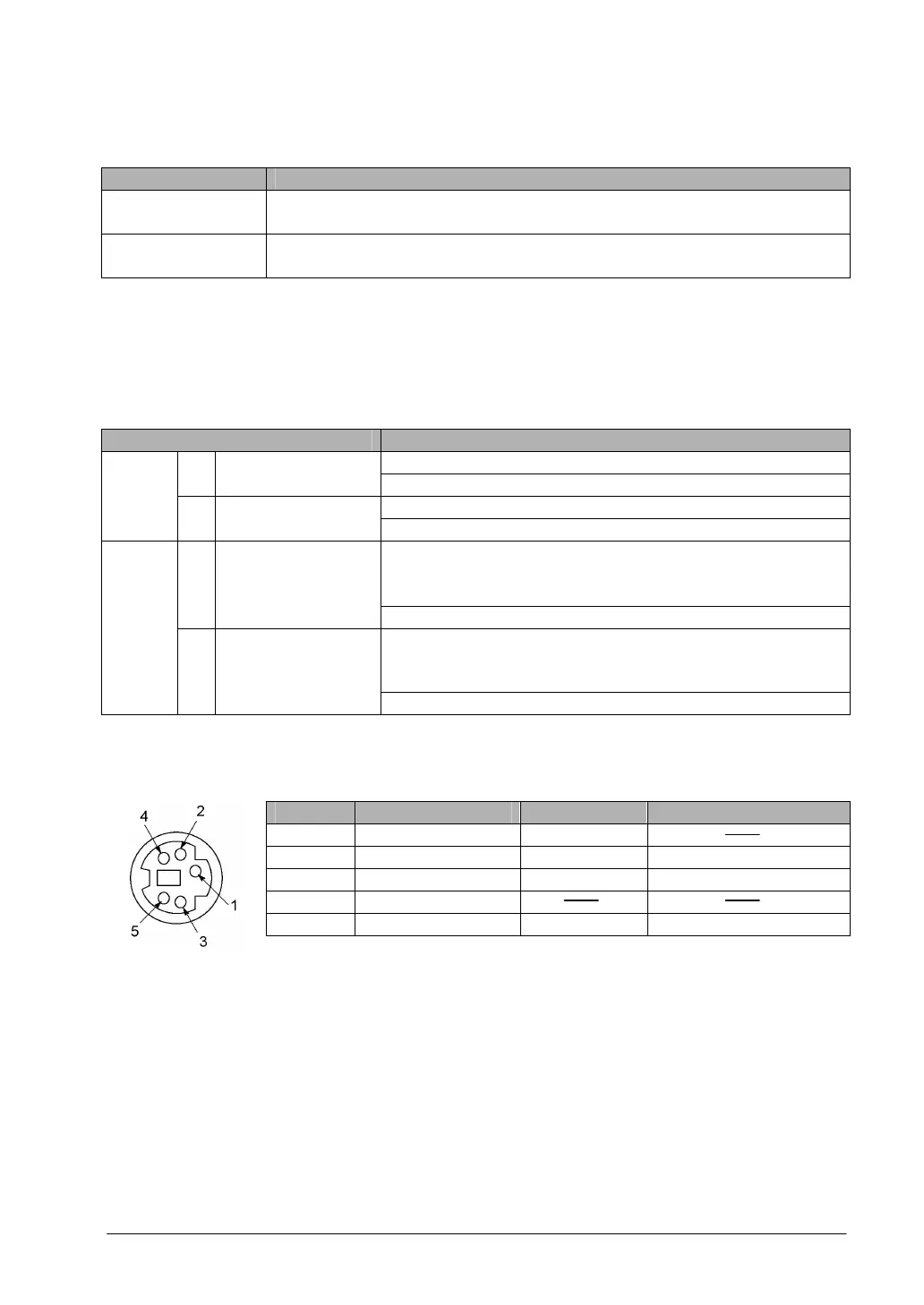
④ Tool port (RS232C)
This port is used to connect a programming tool.
A commercial mini-DIN 5-pin connector is used for the Tool port on the control unit.
Pin No. Signal name Abbreviation Signal direction
1 Signal Ground SG
2 Transmitted Data SD Unit → External device
3 Received Data RD Unit ← External device
4 (Not used)
5 +5V +5V Unit → External device
• The followings are the default settings set when the unit is shipped from the factory. The system
register should be used to change these.
- Baud rate …….. 9600 bps
- Character bit …. 8 bit
- Parity check ….. Odd parity
- Stop bit length .. 1 bit
⑤ Input connector
⑥ Input indicator LEDs
⑦ Output connector