3-11
How to access the memory unit
The following instructions are used to access the expansion data memory unit to the control unit.
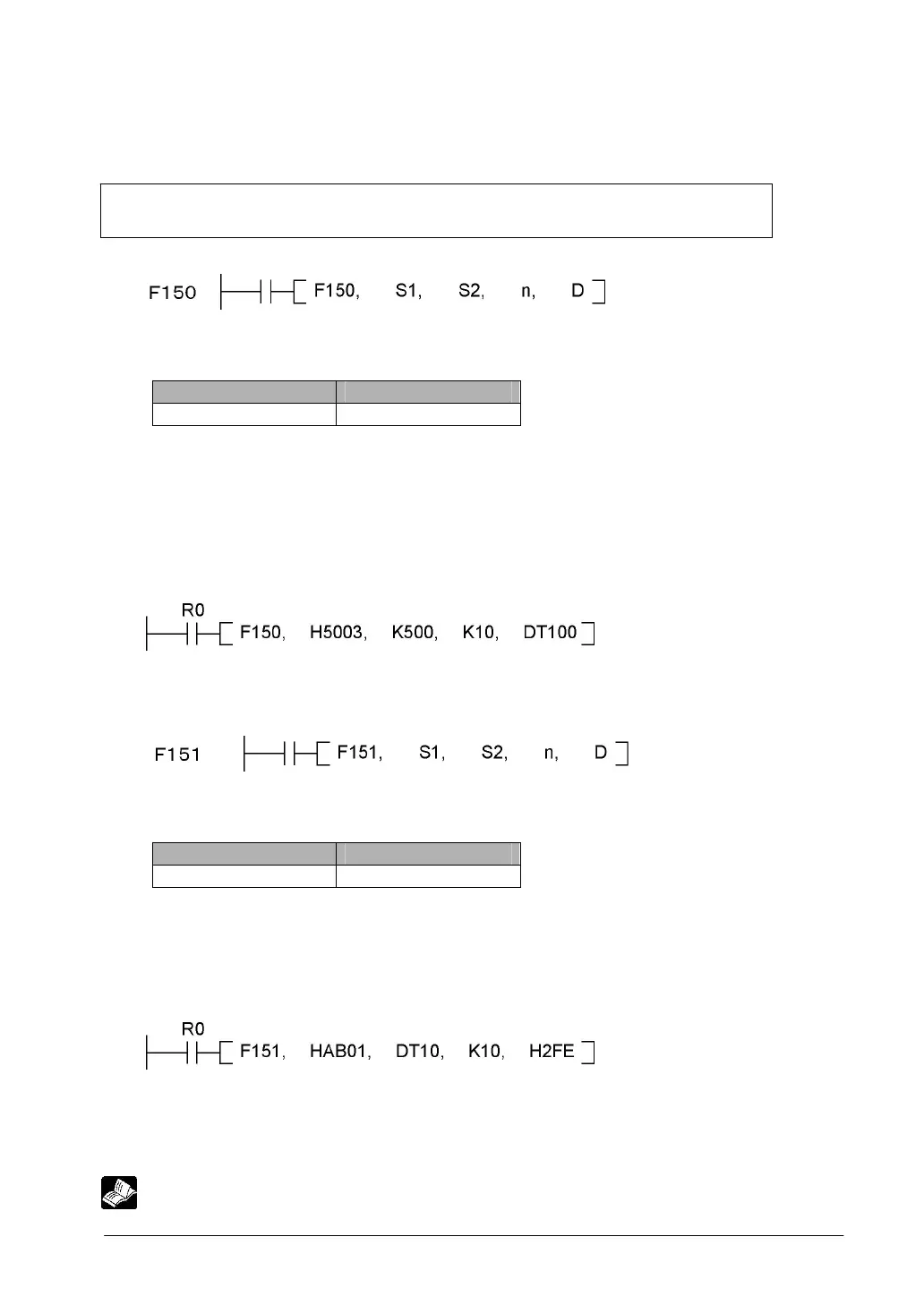
1. F150 instruction (To read data from the expansion data memory unit to the control unit)
2. F151 instruction (To write data to the expansion data memory unit from the control unit)
1.
S1: The area for specifying the slot No. of an Intelligent I/O unit (this unit) and bank numbers
Specify them in hexadecimal.
Higher byte Lower byte
Bank No. H0 to HFF Slot No. H0 to H3
S2: The first address (word address), K0 to K1023 (H0 to H3FF), for reading the memory of an
intelligent I/O unit (this unit)
The area for specifying addresses in the bank specified in S1
n: No. of words to read, K1 to K1024 (H1 to H400)
D: The first area No. to store read data
[Example]
When R0 is on, 10 words will be read from the address K500 of the bank No. H50 in the expansion
data memory unit installed in the slot No. 03 to store DT100 to DT109 in order.
2.
S1: The area for specifying the slot No. of an Intelligent I/O unit (this unit) and bank numbers
Specify them in hexadecimal.
Higher byte Lower byte
Bank No. H0 to HFF Slot No. H0 to H3
S2: The first area No. of write data
n: No. of words to write, K1 to K1024 (H1 to H400)
D: The first area No. to store write data
[Example]
When R0 is on, the contents of DT10, 11, 12 and higher are written for 10 words in order in the area
starting with the address H2FE of the bank No. HAB in the expansion data memory unit installed in
the slot No. H01.
Reference: <4.3.1 I/O Numbers of Expansion Unit>