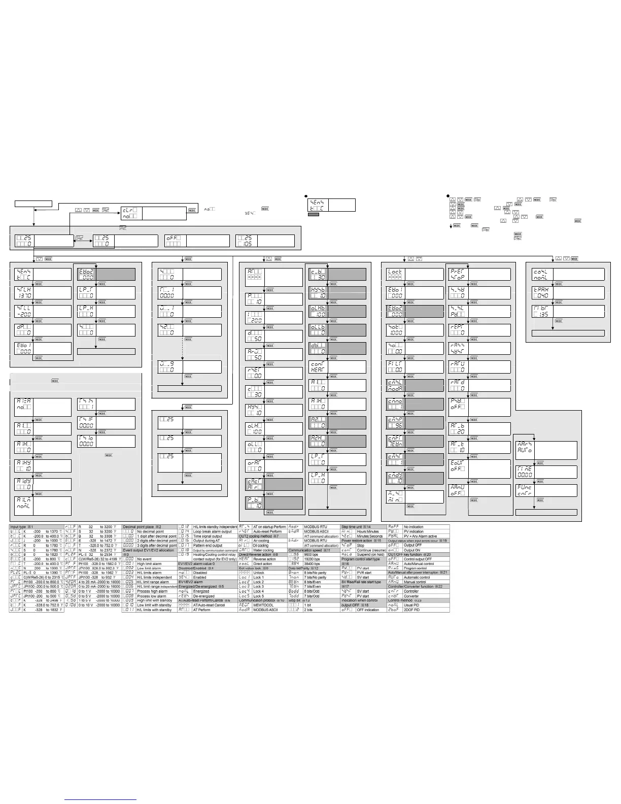
14. Key Operation Flowchart
Power ON
+ + + (3 sec) Data clear
Yes/No
If (Data clear No) is selected, and is pressed, the unit
will revert to PV/SV Display. If (Data clear Yes) is selected,
theunit automatically reverts to PV/SV Display after data is cleared.
Starts from previous
status(last shutdown).
RUN Mode
By pressing the key for approx. 1 sec, one of the following items selected in [OUT/OFF key function] appears.
Program Control Control Output OFF Function Auto/Manual Control
PV/SV Display (1sec) Program control Control output OFF Manual control
(*1) RUN (MV flashes.)
+ (3 sec) + + (3 sec)
+ + (5 sec)
Initial Setting Mode Main Setting Mode Sub Setting Mode Engineering Mode Engineering Mode 2
Input type ※1 Event output EV2 SV1 AT/Auto-reset OUT2 proportion- Set value lock Power restore Control method ※23
[1] allocation ※3[6] [10] Perform/Cancel al cycle [50] ※9 [62] action ※15 [75] [90]
※6 [37]
Scaling high limit Loop break alarm Step 1 time OUT2 ON/OFF Event output Program start Proportional gain 2DOF
[2] Time [7] [11] OUT1 proportion- Hysteresis [51] EV1 allocation temperature [76] coefficient (α) Set value
al band [38] [63] [91]
Scaling low limit Loop break alarm Step 1 wait value OUT2 high limit Event output Program control Integral 2DOF
[3] Span [8] [12] Integral time [52] EV2 allocation start type ※16 [77] coefficient (β) Set value
[39] [64] [92]
Decimal point SV1 SV2 OUT2 low limit Sensor correction Number of
place ※2 [4] [9] [13] Derivative time [53] Coefficient [65] repetitions [78] Reverts to RUN mode.
[40]
Event output EV1 Overlap/Dead Sensor correction SV Rise/Fall rate
allocation ※3 [5] Reverts to RUN mode. ARW Band [54] [66] start type ※17 [79]
Indicates setting items
for Steps 2 to 9.
(*3)
[41]
Step 9 wait value Direct/Reverse PV filter time SV rise rate
[36] Manual reset action ※8 [55] constant [67] [80]
[42]
If Alarm output (001 to 012) or Time signal output (015) is selected in [Event output
EV1/EV2 allocation], and key is pressed, the following items will be indicated.
EV1 alarm value Communication SV fall rate
Reverts to RUN mode. OUT1 proportion- [56] protocol ※10 (*6) [81]
If ‘Alarm output’ is selected in If ‘Time signal output’ is selected
[Event output EV1 allocation] in [Event output EV1 allocation]
al cycle [43] [68]
EV1 alarm value 0 TS1 output EV1 high limit Instrument Indication when
Enabled/Disabled step number [G] (3 sec)(*4) OUT1 ON/OFF alarm value [57] number (*6) [69] control output OFF
※4 [A] Monitor Mode Hysteresis [44] ※18 [82]
TS1 OFF time MV indication EV2 alarm value Communication
EV1 alarm value [H] [MV] (Decimal point flashes.) OUT1 high limit [58] speed ※11 (*6) AT bias
[B] [45] [70] [83]
TS1 ON time Remaining time EV2 high limit Data bit/Parity
EV1 high limit [I] [Remaining time] (*5) OUT1 low limit alarm value [59] ※12 (*6) [71] AT gain Auto/Manual after
alarm value [C] [46] [84] power interruption
Current step Loop break alarm Stop bit ※13 (*6) ※21 [87]
EV1 alarm [Step number OUT1 time [60] [72] Output status when
Hysteresis [D] number] (*5)(*6) rate-of-change input errors occur Indication time
[47] Loop break alarm Response delay ※19 [85] [88]
EV1 alarm OUT2 cooling span [61] time (*6) [73]
delay time [E] Reverts to RUN mode. method ※7 [48] OUT/OFF key Controller/
By pressing the key, the unit
moves to the item after [Event output
EV1 allocation].
If Alarm output (001 to 012) or Time
signal output (015) is selected in [Event
output EV2 allocation], read EV2, TS2
for EV1, TS1.
Step time unit function ※20 [86] Converter ※22
EV1 alarm Ener- OUT2 proportion- ※14 [74] [89]
gized/De-energized al band [49]
※5 [F] Reverts to RUN mode. Revertsto RUN mode.
About Setting Item
• Upper left: PV Display: Indicates setting characters
• Lower left: SV Display: Indicates factory default.
• Right side: Indicates the setting item.
: Appears when Event output EV2 and Communication function are designated.
(*1) If ‘Program control’ is selected in [OUT/OFF key function], the unit will enter
Standby mode (Program control waiting).
(*2) Not available if ‘Programcontrol’is selected in [OUT/OFF key function].
(*3) If ‘Program control’ is selected in [OUT/OFF key function], SV2 to SV9, Steps 1 to
9 time, Steps 1 to 9 wait value are available.
(*4) Theunit cannot proceed to Monitor mode if it is in Standby of Program control.
(*5) Availableonly when ‘Program control’is selected in [OUT/OFF key function].
Input type
Key Operation
• + + + (3 sec): Press andhold , , and (in that order) for approx. 3 sec.
• + (3 sec): Press andhold the , keys (in that order)together forapprox. 3 sec.
• + : Press and hold the , keys (in that order)together.
• + (3 sec): Press andhold the , keys(in that order) together for approx. 3 sec.
• + + (5 sec): Press andhold the , and keys (inthat order) together for approx. 5sec.
• Set (or select) each item with the or key, and register the value with the key.
• : If the key is pressed, the unit will move to the next item, illustrated by an arrow.
Pressing the key moves back to the previous item.
• To revert to RUN mode, press and hold the key for approx. 3 sec while in any mode.
• To revert to RUN mode, press and hold the key for approx. 3 sec while in any mode.
If ‘Control output OFF function’ is selected in [OUT/OFF key function], the unit will enter Control output OFF
status. If ‘Auto/Manual control’ is selected, the unit will enter Manualcontrol status.
If ‘Program control’ is selected, the unit will enter Program control RUN or Standby mode.

 Loading...