9. Attached Function
9.1 Input Value Correction
Input value can be corrected in [Sensor correction coefficient] and [Sensor correction] in Engineering
mode.
In [Sensor correction coefficient], set the slope of temperature change.
In [Sensor correction], set the difference between temperatures before correction and after correction.
PV after input correction is expressed with the following formula.
PV after input correction = Current PV x Sensor correction coefficient + (Sensor correction value)
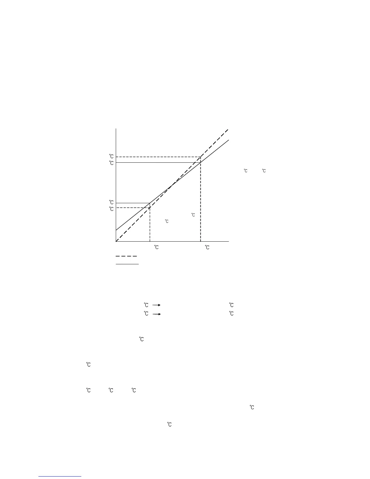
The following shows an example of input value correction using ‘Sensor correction coefficient’ and
‘Sensor correction value’.
(Fig.9.1-1)
(1) Select any 2 points of PV to be corrected, and determine the PV after correction.
PV before correction: 300 PV after correction: 340
PV before correction: 750 PV after correction: 700
(2) Calculate Sensor correction coefficient from Step (1).
(Y' – X') / (Y – X) = (700 – 340) / (750 - 300) = 0.8
(3) Enter a PV value of 300 using an mV generator or dial resistor.
(4) Set Step (2) value as a Sensor correction coefficient.
(5) Read the PV.
240 will be indicated.
(6) Calculate the sensor correction value.
Calculate the difference between ‘PV after correction’ and Step (5) PV.
340 – 240 = 100
(7) Set Step (6) value as a Sensor correction value.
(8) Enter an electromotive force or resistance value equivalent to 750 using an mV generator
or dial resistor.
(9) Read the PV, and confirm that 700 is indicated.
300
300
340
750
750
700
After correction
Before correction
Slope before correction
Slope after correction
Y
Y’
X’
X
Corrected from 750 to 700 .
Corrected from 300