26
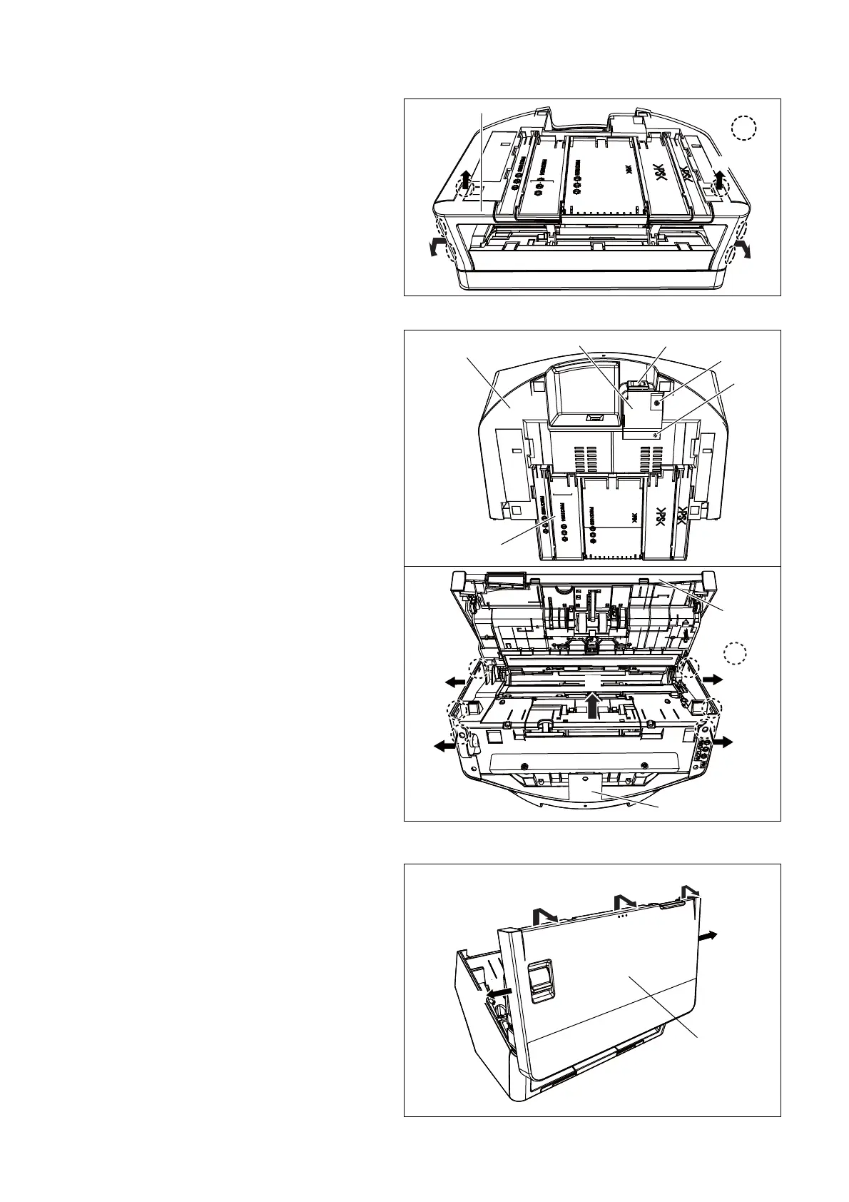
7.2.4. Front Cover
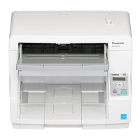
7.2.5. Back Cover
7.2.6. Top Cover
(1) Pull the Front Cover (2 arrows 1) at the same time to unlock
3 hooks.
(2) Pull the Front Cover (2 arrows 2) at the same time to unlock
3 hooks.
(3) Remove the Front Cover.
(1) Remove the Front Cover. (See
Front Cover (P. 2 6))
(2) Remove the screw C and H.
(3) Remove the AC Inlet cover.
(4) Remove the AC Inlet from the Back Cover.
(5) Open the ADF Door.
(6) Unlock the 2 hooks of the back side, while pulling the Back
Cover (2 arrows 1).
(7) Unlock the 4 hooks of the upper side, while expanding the
Back Cover (2 arrows 2).
(8) Remove Back Cover (arrow 3).
(1) Pull the Top Cover (2 arrows 1) at the same time to unlock 2
hooks
* See
PANEL SWITCH Board and LCD PANEL Board (KV-S10xxC)
(P. 2 7 ) for the detail position of the hooks.
(2) Pull the Top Cover (1 arrows 2) to unlock the center hook.
(3) Pull the Top Cover (2 arrows 3) at the same time to unlock 2
hooks.
(4) Remove the Top Cover and disconnect the FFC cable.
* See
PANEL SWITCH Board and LCD PANEL Board (KV-S10xxC)
(
P. 2 7 ) for the cable position.
AC Inlet Cover AC Inlet
Exit Tray
C
Back Cover
H
Back Cover
ADF Door
Hook
1
1
2
3
2

 Loading...