TROUBLESHOOTING
IPA Hardware Installation Guide 75
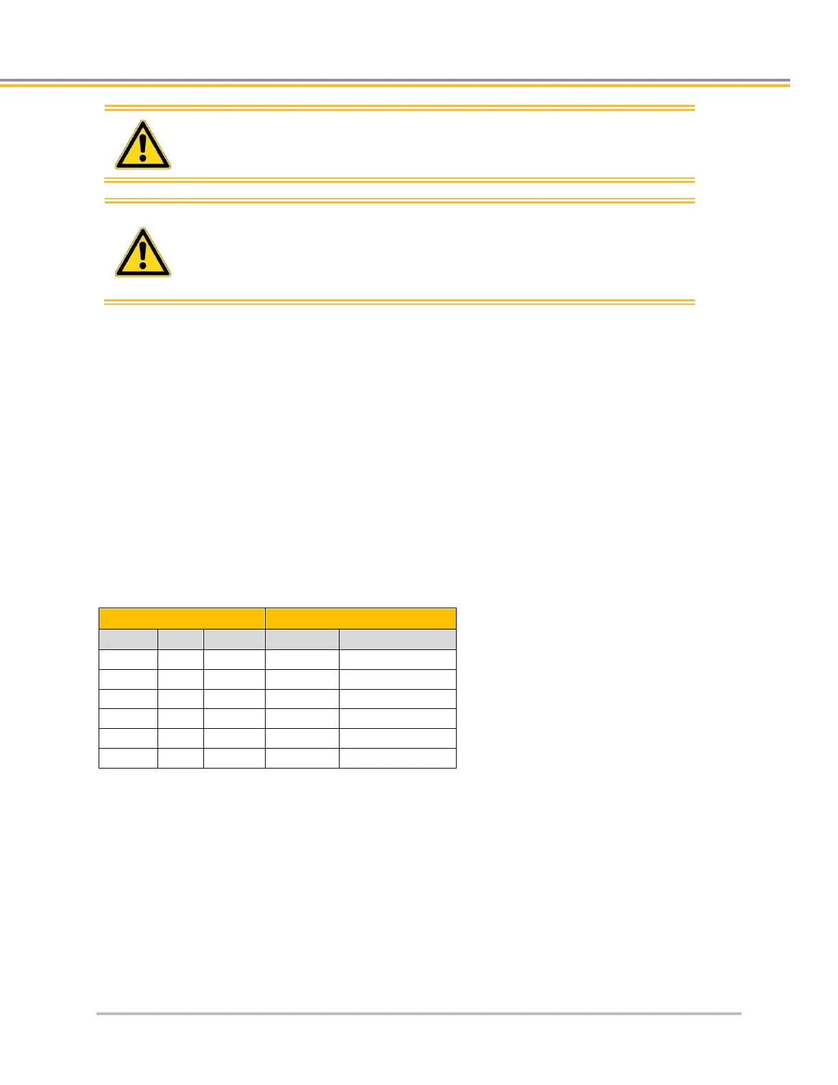
Warning: This procedure could damage the motor. Slowly increase the
voltage until the motor moves. Do not exceed the rated
current.
High-performance motion control equipment is capable of
producing rapid movement and very high forces. Unexpected
motion may occur especially during the development of
controller programs. KEEP WELL CLEAR of any machinery
driven by stepper or servo motors. Never touch any part of the
equipment while it is in operation.
3 If THALL reports a 1, 2, or 4, change SHALL from either 0 to 1 or from 1 to 0. After you change SHALL,
reset the drive/controller.
4 Change the Hall wires until THALL reports a value of 6.
5 Connect motor wires U and W and slowly apply a positive voltage with respect to V.
6 If THALL does not report a value of 3, change Hall wires B and C. If THALL reports a value of 3, the
wires are connected correctly.
The following table summarizes phase voltages and their corresponding Hall states. Starting with SHALL=Ø and
the phase voltages as shown, the THALL command should report the Hall states that match the “Correct”
column. If instead THALL reports Hall states that match the “Use SHALL=1” column, enter SHALL=1 and reset
the drive/controller. The Hall states should now match the “Correct” column. For more information, see Figure
34 on page 76.
Configuring Hall Sensors
Figure 34 illustrates the alignment of phases U, V, and W with Halls 1, 2, and 3 as viewed from the front of the
shaft. The illustration assumes the following:
Hall signals that are High equal TRUE signals.
Hall 1 is the least significant bit (LSB).
Hall 3 is the most significant bit (MSB).
There is one hall cycle and one electrical cycle per pole pair on the motor.