ADDITIONAL SPECIFICATIONS
88 IPA Hardware Installation Guide
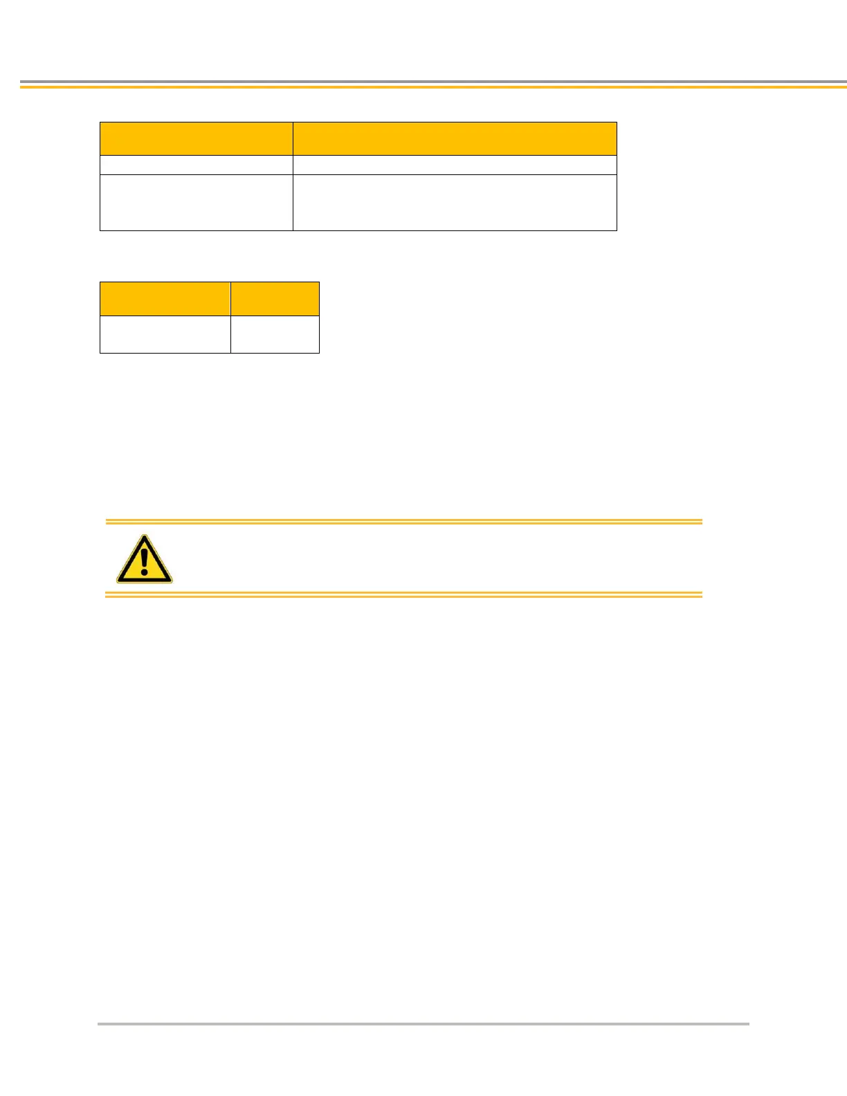
Threshold Voltage
Power to motor is turned off
Drive status word is updated via Ethernet to the PC
(See the table “LED Over-Voltage Fault”)
LED Over-Voltage Fault
Yellow & 4 Green
(blinking)
Resetting the fault
To clear the latched fault, choose one of the following methods:
Cycle power to the drive/controller.
–or–
Open ACR-View and issue the DRIVE RES AXIS0 command to the IPA.
Warning: Over-voltage protection monitors only the motor output
terminals (DC motor bus). It does not protect against an over
voltage on the AC input terminals, which can permanently
damage the drive/controller.
Current Foldback
The IPA’s current foldback circuit helps to protect the unit from damage due to prolonged high currents. If your
unit is operating above its continuous current rating, see Figure 35 to predict the number of seconds until foldback
will occur. For example, the figure shows that at the drive/controller’s peak current rating (250% of continuous),
foldback will occur after six seconds. After operating at the its peak current, the IPA will reduce the
drive/controller current to 80% of the its continuous rating for 60 seconds. This is to ensure the unit’s average
continuous current rating is not exceeded.