ELECTRICAL INSTALLATION
IPA Hardware Installation Guide 51
Brake Relay to Motors without Full Wave Rectifiers
When using Parker MaxPlus motors, Parker motors with serial numbers less than 010904xxxxx, or non-Parker
motors, you must install a fly-back diode. Consult the specifications or the manufacturer of your motor.
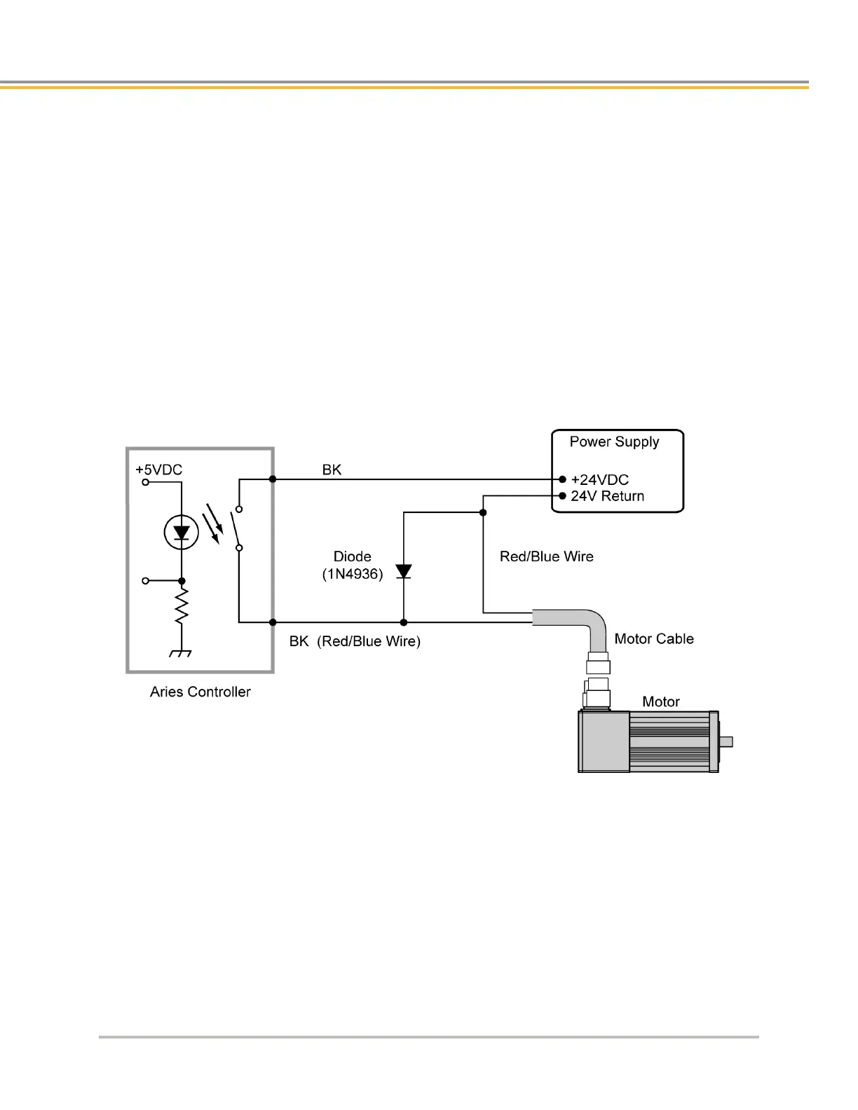
1 Connect one red/blue brake wire (Parker Motor cable or equivalent) to one BK terminal (located on the
Motor connector.
2 Connect the second red/blue brake wire (Parker Motor cable or equivalent) to the 24V return on your
power supply.
3 Between the two red/blue wires, connect the fly-back diode.
4 Connect the +24 VDC power supply to the second BK terminal.
The following figure shows a typical installation.
Figure 19. - Brake Relay Connection for Motor without Full Wave Rectifiers