ELECTRICAL INSTALLATION
40 IPA Hardware Installation Guide
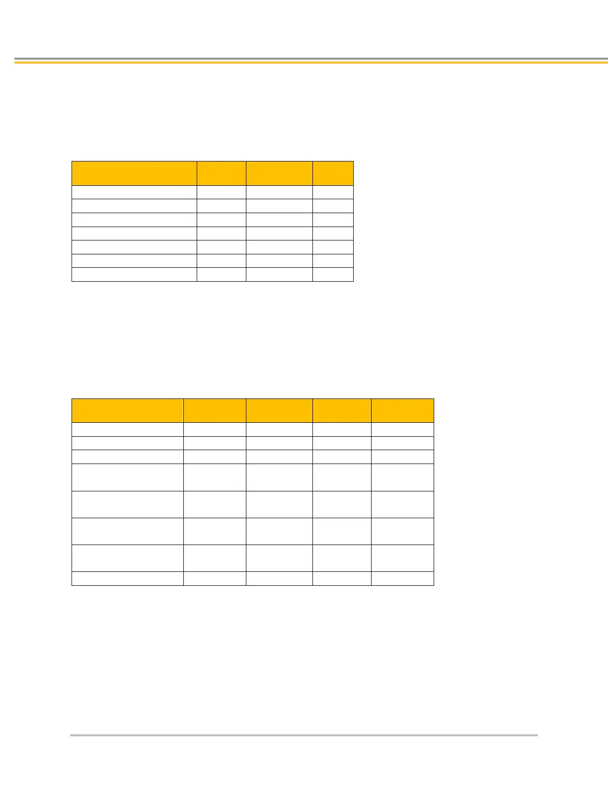
Inputs—General Purpose
These slow inputs are optically isolated. Current is limited internally for input voltage control of 5 to 24 volt logic.
The Anode (+) and Cathode (−) optocoupler inputs are on separate connector pins to allow significant flexibility in
wiring to different styles of interface.
Inputs —General Purpose
Note that all parameters are at the connector pin.
Outputs—General Purpose
The general purpose outputs are optically isolated and current limited. Both sides of the MOSFET output structure
are brought to the pins to allow significant flexibility in wiring to different styles of interface.
Outputs —General Purpose
On-time voltage drop
IL ≤ 10 mA
On-time voltage drop
10 mA < IL ≤ 100 mA
Load current,
IL (TA ≤ 35C)
Load current,
IL (35C < TA ≤ 50C)
Short circuit trip current
Note that all parameters are at the connector pin.
X7 – Auxiliary (Control Power, Torque Enable,
Analog Input)
The Auxiliary connector on the IPA allows the user access to three separate functions on the product: control
power, torque enable, and two analog inputs.