TROUBLESHOOTING
68 IPA Hardware Installation Guide
Motor Control
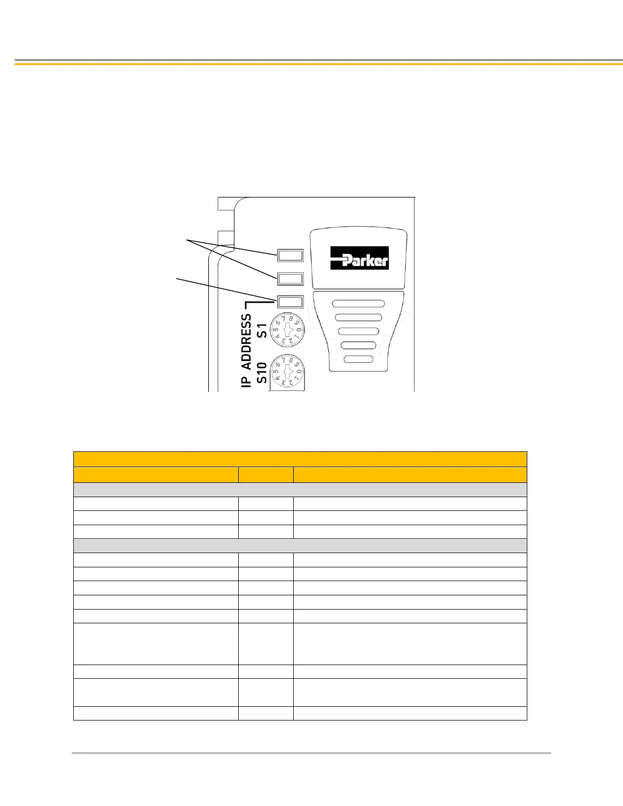
The first step in troubleshooting motor-control issues is to examine the Drive/Controller Status LEDs (Figure 32).
Use the following table to determine the indicated condition. Use the additional information in this section to take
corrective action. On power-up, the LED pattern will flash through the various boot stages before settling into one
of the patterns listed below.
Figure 32. - Drive/Controller Status LEDs
Drive Status Indicator LED Descriptions
Controller Status LED Illumination States
Yellow (flashes during Regeneration)
Enabled, Regeneration active
Yellow/Green (alternating)
Drive/Controller Disabled
Disabled, no bridge power
Yellow & 1 Green (flashing)
Yellow & 2 Green (flashing)
Disabled, Feedback fault (Hall error or Encoder loss)
Yellow & 3 Green (flashing)
Yellow & 4 Green (flashing)
Disabled, other fault (Undervoltage, Overvoltage,
Motor Configuration error, Motor Regeneration
fault, or Network Loss fault)
Yellow & 5 Green (flashing)
Disabled, Drive Parameter fault
Hardware watchdog fault
*Ethernet LED will also be Red