INTRODUCTION
IPA Hardware Installation Guide 17
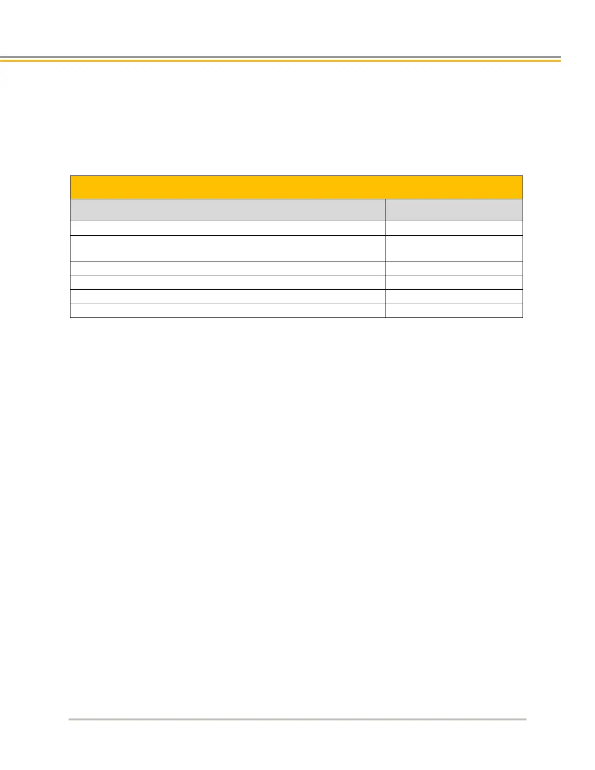
Checking Your Shipment
Confirm that you have received all items in the table below. These items ship with the following drives: IPA. If you
are missing an item, call the factory. For contact information, see Contact Information for Technical Assistance at
the beginning of this guide.
The following items ship with the IPA drives:
IPA Connector, 6 pin (Motor)
Connector, 7 pin (Power)
with jumper wires (22AWG) (x2)
43-021069-01
44-015741-01
Connector 2 pin (Hiperface DSL)
Connector, 2x6 pin (EN, AUX)
Illustrations in this Installation Guide
Typically, the illustrations in this guide show the IPA, which is representative of all IPA Controller models. All
models have the same external features and housing, although the power level and height of the heat sink fins
differ.
Assumptions of Technical Experience
The IPA Controller is designed for industrial applications. To effectively install and troubleshoot the drive, you
must have a fundamental understanding of the following:
Motion control applications
Electromechanical actuators
Voltage, current, switches, and other electrical concepts
Basic Programming
Technical Support
For solutions to questions about implementing the drive, first refer to this manual. If you cannot find the answer in
this documentation, contact your local Automation Technology Center (ATC) or distributor for assistance.
If you need to talk to our in-house Application Engineers, please contact us at the telephone numbers listed in the
“Contact Information for Technical Assistance” table on page 3.