APPENDIX B
IPA Hardware Installation Guide 105
This applications note clarifies the connections with the IForce and Ripped series motors and positioners to the
IPA. IForce and Ripped coils and positioners can be supplied with flying lead cables, covered in this appendix. For
positioners with the connector box, see “Appendix C.”
IForce/Ripped to IPA-Controller Wiring
The IForce and Ripped coils have different color codes based upon the wiring option (such as WD3 or WD7 in
the part number). The IForce positioners (T1, T2, T3 and T4) use coils with WD2 wiring option, a separate
MHED module that includes optical limits/ home sensors and magnetic hall-effect feedback, and the encoder
readhead and scale. The Ripped positioners (TR07, TR10, TR16) use HED connector modules that include both
magnetic limits/home and hall-sensors feedback, and encoder readhead and scale.
In 2008 Parker began changing wire color codes, both old and new are shown for reference.
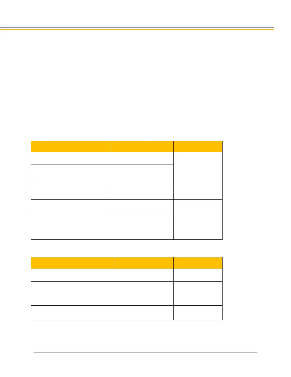
T1, T2, T3 Positioners/110, 210, 310 Coils with Options WD0/WD1/WD2/WD7
Drain (coils)
Green/Yellow (Positioners)
T4, TR7, TR10, TR16 Positioners/R7, R10, R16, 410 and ML50 Coils/110, 210, 310 Coils with Options
WD3/WD4
Drain (coils)
Green/Yellow (Positioners)