EasyManuals Logo

Parker IPA04-HC User Manual

Parker IPA04-HC
128 pages
To Next Page IconTo Next Page
To Previous Page IconTo Previous Page
Page #106 background imageLoading...
Page #106 background image
APPENDIX B
106 IPA Hardware Installation Guide
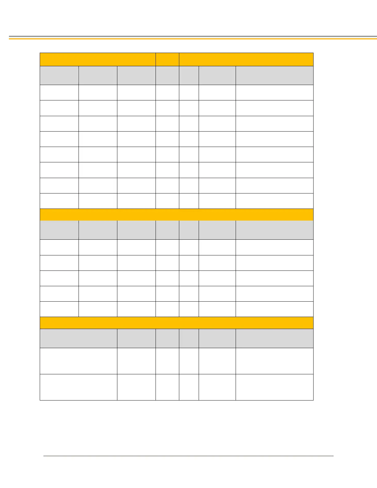
Encoder, Hall and Thermal Sensor Connections
Encoder Cable
Note
IPA Feedback Connector
Function
LME
Magnetic
RGH
Optical
Pin
#
Signal
Description
+5V
Brown
Brown
4
+5 VDC
+5 VDC Encoder power
Ground
White
White
3
DGND
Encoder power return
A/
Yellow
Yellow
*
8
ENC A+
Encoder A Channel in
A+
Green
Green
*
7
ENC A
Encoder A Channel in
B+
Blue
Blue
12
ENC B+
Encoder B Channel in
B-
Red
Red
11
ENC B-
Encoder B Channel in
Z+
Black
Pink
1
ENC Z+
Encoder Z Channel in
Z-
Orange
Grey
2
ENC Z
Encoder Z Channel in
Hall Effect Cable
Function
Hall Type
1
Hall Type
2
Note
Pin
#
Signal
Description
+5V
Black
Black
5
+5 VDC
+5 VDC Hall power
Ground
White
White
6
DGND
Hall power return
Hall C
Yellow
Brown
**
9
Hall 1
Hall 1 input
Hall B
Blue
Blue
**
13
Hall 2
Hall 2 input
Hall A
Green
Green
**
14
Hall 3
Hall 3 input
Motor Cable
Temp Style1
Temp
Style2
Note
Pin
#
Signal
Description
Yellow
Grey
10
Thermal+
Motor thermal
switch/thermistor
Orange
Violet
15
Thermal-
Motor thermal
switch/thermistor
Hall Type 1: All Positioners with flying leads, all coils not listed in Hall Type 2
Hall Type 2: Coils 210, 310, 410, with WD7/C
Temp Style 1: All Positioners with flying leads, Coils with WD0, WD1, WD2, WD7
Temp Style 2: Coils with WD3, WD4 options
* The encoder's A+ and A- are reversed at the IPA drive, A/ and A respectively.
** Halls C/B/A are reversed at the IPA, Hall 1/2/3 respectively

Table of Contents

Questions and Answers:

Question and Answer IconNeed help?

Do you have a question about the Parker IPA04-HC and is the answer not in the manual?

Parker IPA04-HC Specifications

General IconGeneral
BrandParker
ModelIPA04-HC
CategoryController
LanguageEnglish

Related product manuals