ELECTRICAL INSTALLATION
IPA Hardware Installation Guide 47
Multiple Drive/Controller Installations
In a typical cabinet installation, a single mains line connects to a terminal bus inside the cabinet. From the terminal
bus, make individual connections for Mains and Control Power to the corresponding connector(s) on each
drive/controller. Be sure to install fuses for each drive between the terminal bus and the drive.
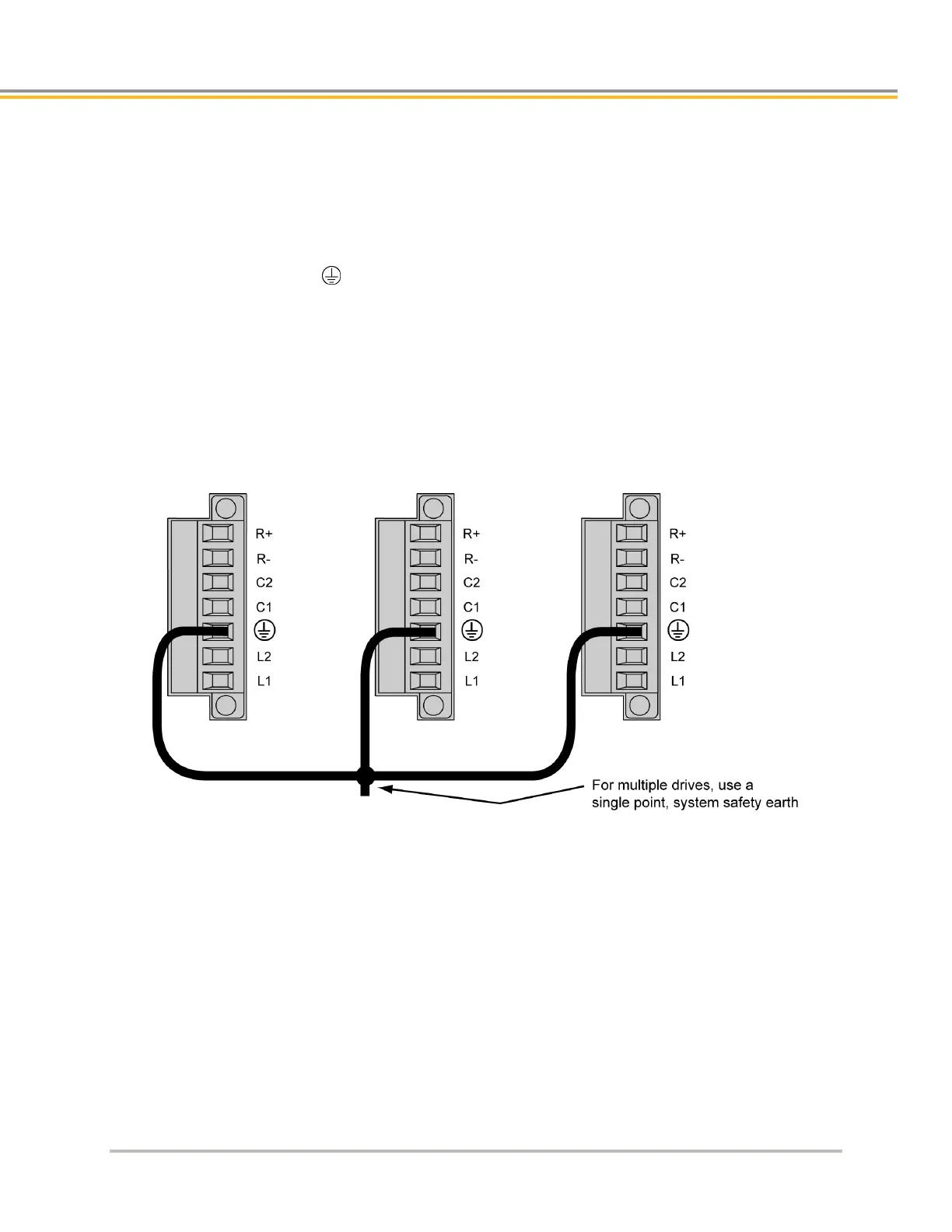
Tie each drive’s Protective Earth conductor terminal directly to the system safety earth location as shown in
Figure 16. Under normal operation, no current should flow through the Protective Earth ground.
Safety Earth Connection
For multiple drive installations, Parker Hannifin recommends a single point or “star” safety earth configuration. The
following figure represents a typical star safety earth connection.
Figure 16. - Multiple Drives Safety Earth Connection
Brake Relay (Optional)
The Brake Relay connection (on the Output Power connector) provides a safety feature for your motion control
system, particularly for vertical applications. The drive/controller acts as a control switch for the motor brake (if a
brake is present). When 24V is applied from an outside power supply through the drive’s Brake Relay (BK)
terminals, the motor brake is disabled. When the power supply is interrupted, or the drive/controller faults or is
disabled, the brake is enabled and stops shaft rotation.