TORQUE ENABLE SAFETY CIRCUITRY
80 IPA Hardware Installation Guide
User Connections
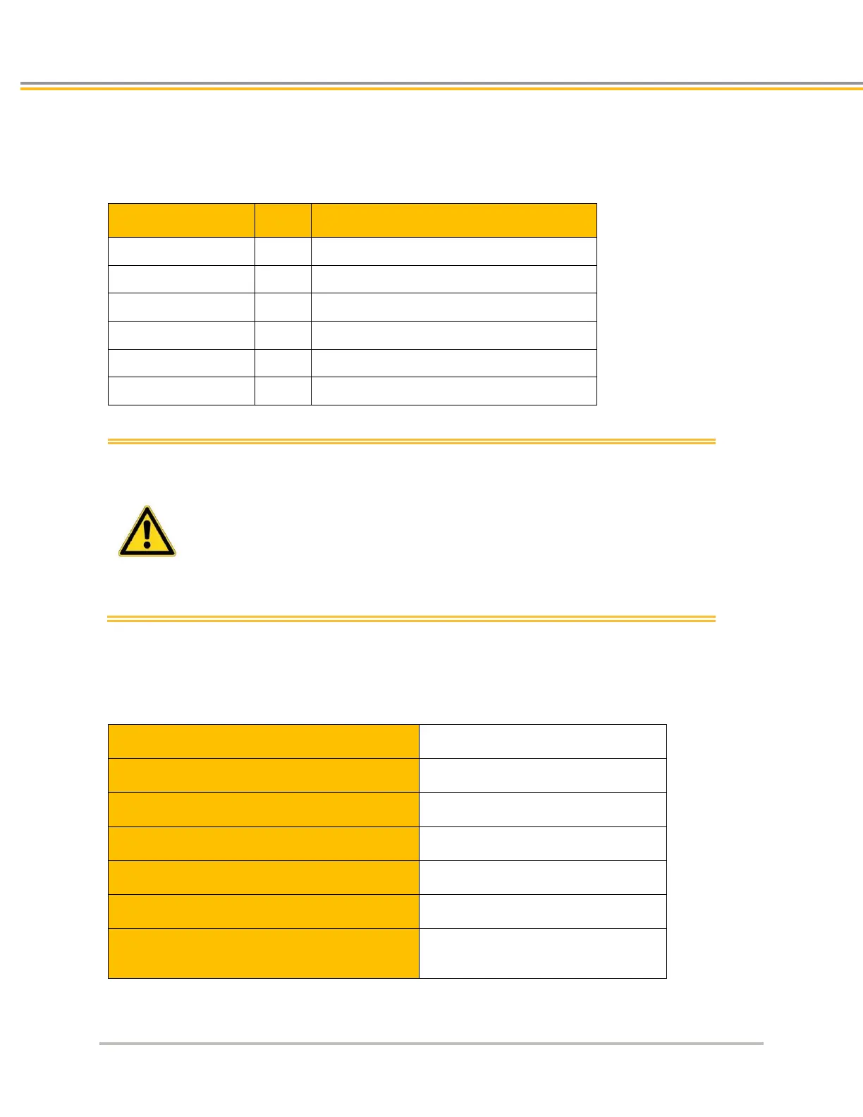
The Torque Enable terminals are on the Auxiliary connector mounted on the top of the IPA. Terminal
designations are:
Bypass power for TE (limited to 30mA)
Negative input torque enable input 1
Negative input torque enable input 2
Warning: The IPA comes with the Torque Enable connector pre-wired to
always enable the drive’s ability to provide torque. In order to
disable torque and wire the drive to your safety system, you
must remove the two 3-pronged jumpers between pins 2, 3, 4
and pins 8, 9, 10.
The IPA pin TRQ_EN_24V is internally limited to 30mA and is
intended only as a bypass of the Torque Enable circuitry for
those applications wishing to disable this feature. Do not power
external circuitry with this output.
Torque Enable Technical Specification
Inputs Specification
Recommended input voltage for low level
Recommended input voltage for high level
Typical input threshold voltage
Indeterminate input range
+5V to +15V. Function is undefined.
Absolute maximum input voltage
2.3 sec typical:
< 1.6 sec will not generate a fault
> 3.0 sec will generate a fault.