ELECTRICAL INSTALLATION
IPA Hardware Installation Guide 37
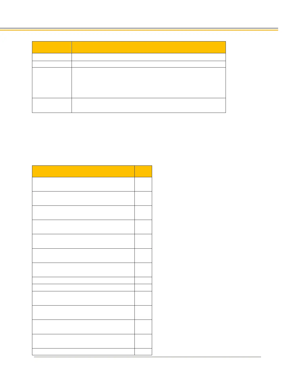
Drive I/O Connector Specification—Mating Connector
1
25-Pin D-Subminiature (male connector)
AMP Part Number
748474-1 includes:
1658648-1 connector
shield
enclosure
two jack screws
(does not include contacts or ferrules)
Gold Flash—Amp Part Number 748333-7
30μ”Gold—AMP Part Number 748333-4
1
Mating connectors are not provided with the drive.
Drive I/O Connector Pinout
Pinout configuration for the Drive I/O connector is listed in the following table. A box surrounding pins indicates a
requirement for twisted pair wiring.
Drive I/O Connector Pinout
High-Speed Input 4+
High-Speed Input 4–
High-Speed Input 5+ (or Auxiliary Encoder A+) *
High-Speed Input 5– (or Auxiliary Encoder A-) *
High-Speed Input 6+ (or Auxiliary Encoder B+) *
High-Speed Input 6– (or Auxiliary Encoder B-) *
* Can be used as a high-speed input or an auxiliary encoder.