- PCME STACK 990 MANUAL: 19 -
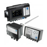
Set address switch (SW100)
Each sensor must have a unique address on the network. The address is set by means of the DIP
switch (SW100). Only switch positions 1 to 6 are used giving valid address settings from 1 to 64.
The illustration above shows address 5. The address switch uses binary coding to calculate the
required address.
For example, to set address number 5: Set switch 1 (binary 1) ON and switch 3 (binary 4) ON (4
+ 1 = 5).
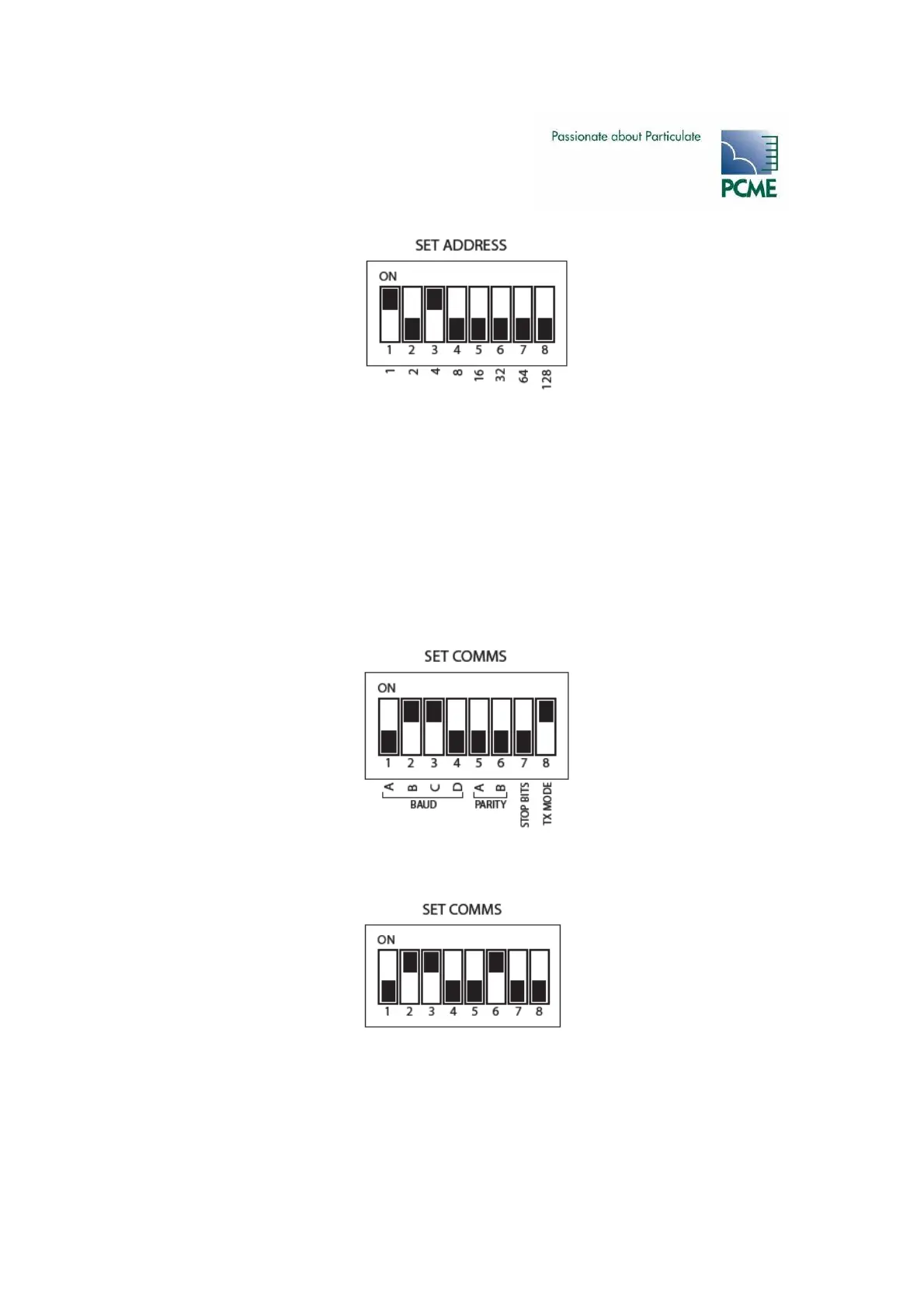
Communication Settings (SW101)
The sensor has two comms settings, ASCII and RTU. The default setting is ASCII: 19200 Baud,
No Parity, 1 Stop Bit, ASCII mode (7-bit). The DIP switch should be set as follows:
RTU is a faster communications protocol but is not available for all devices; refer to the Control
Unit Reference Manual. If RTU mode is required set the DIP switch as follows:
Refit the Sensor Cover and secure with the four screws. Do not over tighten the screws.