- PCME STACK 990 MANUAL: 18 -
For “spur linked” Sensor Systems
Route the input cable through the cable gland nearest to the BUS IN terminals. Make the
connections to the BUS IN terminals as follows from left to right:
BUS IN TERMINAL
*Connect the cable screen to the
earth stud
The same connections are copied at the Spur. At the spur connect the screen to the terminal.
Before refitting the cover the Sensor Unit must be configured in accordance with the Setting Up
instructions.
Cable Routing
When routing cables observe the following:
• Ensure the cable sheath penetrates the Sensor Unit entry gland
• Fit blanking plugs to unused cable entry glands
• Ensure cable entry glands are tightened to the cable
• Support cables at appropriate intervals
• Do not route cables over roofs
3.6 Setting Up
Refer to Figure 3-5 for the location of the set-up switches.
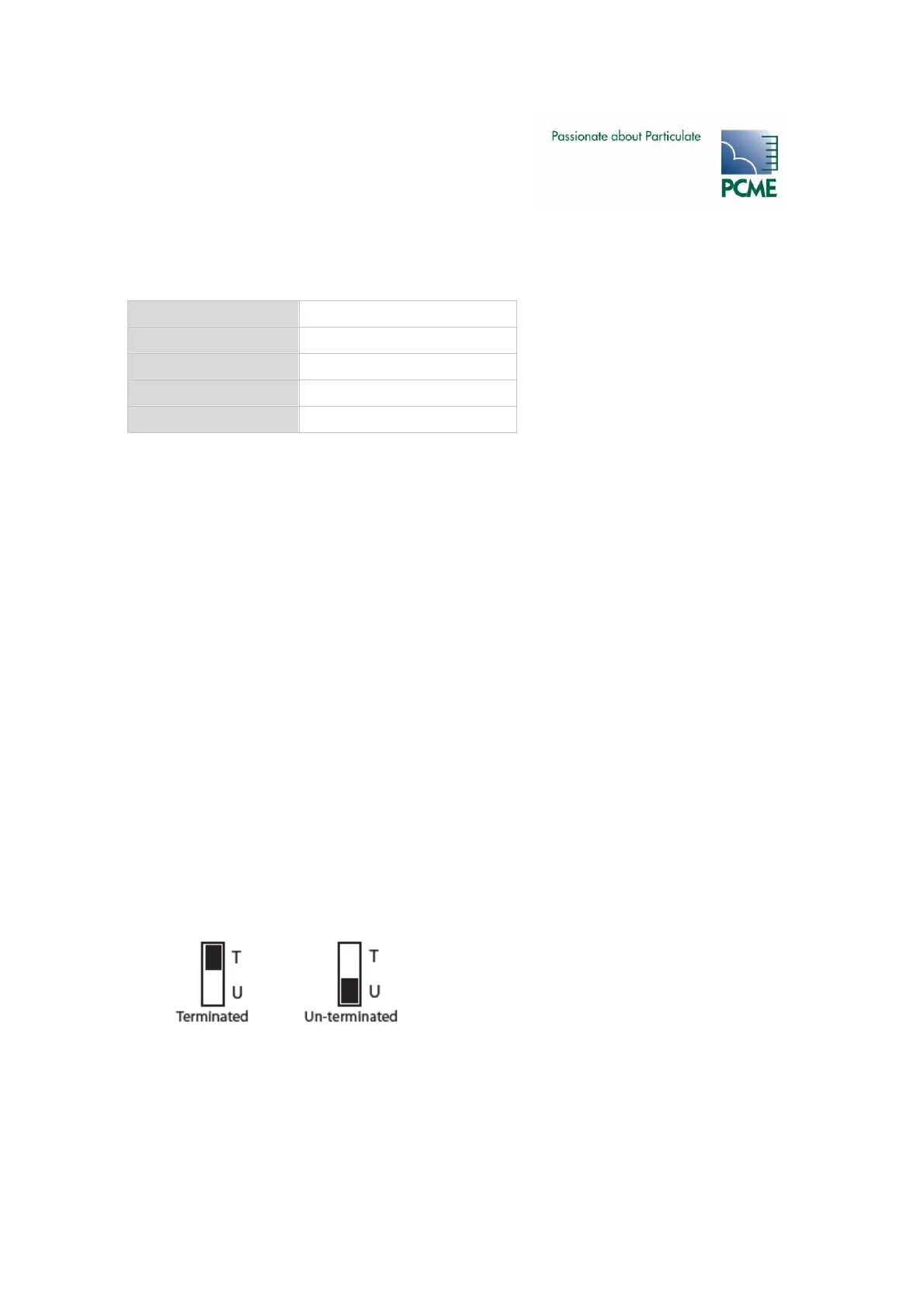
Bus Termination Switch (SW200)
The Bus Termination Switch (SW200) identifies the sensor’s position in the network. Set the
switch to “U” for all sensors in the chain except the last sensor, which must be set to T. For spur-
systems leave all sensors terminated (switch to “T”).
0V Blue
Comms B Orange
Comms A Green
24V Brown
(Screen) Do not use*