EasyManuals Logo

PCME STACK 990 User Manual

PCME STACK 990
79 pages
To Next Page IconTo Next Page
To Previous Page IconTo Previous Page
Page #17 background imageLoading...
Page #17 background image
- PCME STACK 990 MANUAL: 17 -
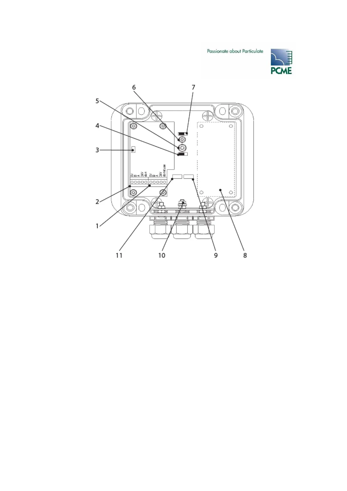
Figure 3-5 PCME Stack 990 Sensor Unit
6
Contamination probe
7 Contamination probe enable/disable
(shown enabled)
8 4-20mA and relay outputs (option)
9 Set comms switch (SW101)
10 Earth stud (cable screen)
11 Set address switch (SW100)
1
BUS OUT
(power and comms
)
2 BUS IN(power and comms)
3 Bus termination switch (SW200)
4 Main probe enable/disable switch
(shown enabled)
5 Main probe

Table of Contents

Questions and Answers:

Question and Answer IconNeed help?

Do you have a question about the PCME STACK 990 and is the answer not in the manual?

PCME STACK 990 Specifications

General IconGeneral
BrandPCME
ModelSTACK 990
CategoryMeasuring Instruments
LanguageEnglish

Related product manuals