- PCME STACK 990 MANUAL: 31 -
5.5 Installation
HAZARDOUS VOLTAGES
THIS EQUIPMENT CONTAINS LETHAL VOLTAGES (100-240VAC 50/60HZ).
MAKE ALL THE DATA CONNECTIONS BEFORE MAKING THE POWER SUPPLY
CONNECTIONS. LEAVE THE RIGHT HAND CABLE GLAND ENTRY (VIEWED
FROM THE FRONT) FREE FOR THE POWER SUPPLY CABLE.
Mounting the Interface Module
Refer to Figures 4-1. Remove the four screws securing the unit front cover and remove the
cover.
Identify the four fixing holes and using suitable fixings secure the unit to a suitable fl at, vertical
surface.
Data Cable Connection
Data cable connections are as follows from left to right:
SENSOR/NETWORK
CONNECTOR
Route the data cable through the cable gland nearest to the SENSOR/NETWORK connector and
make the connections to the terminals.
Connect the cable screen to the nearest earth connection terminal using an eyelet tag.
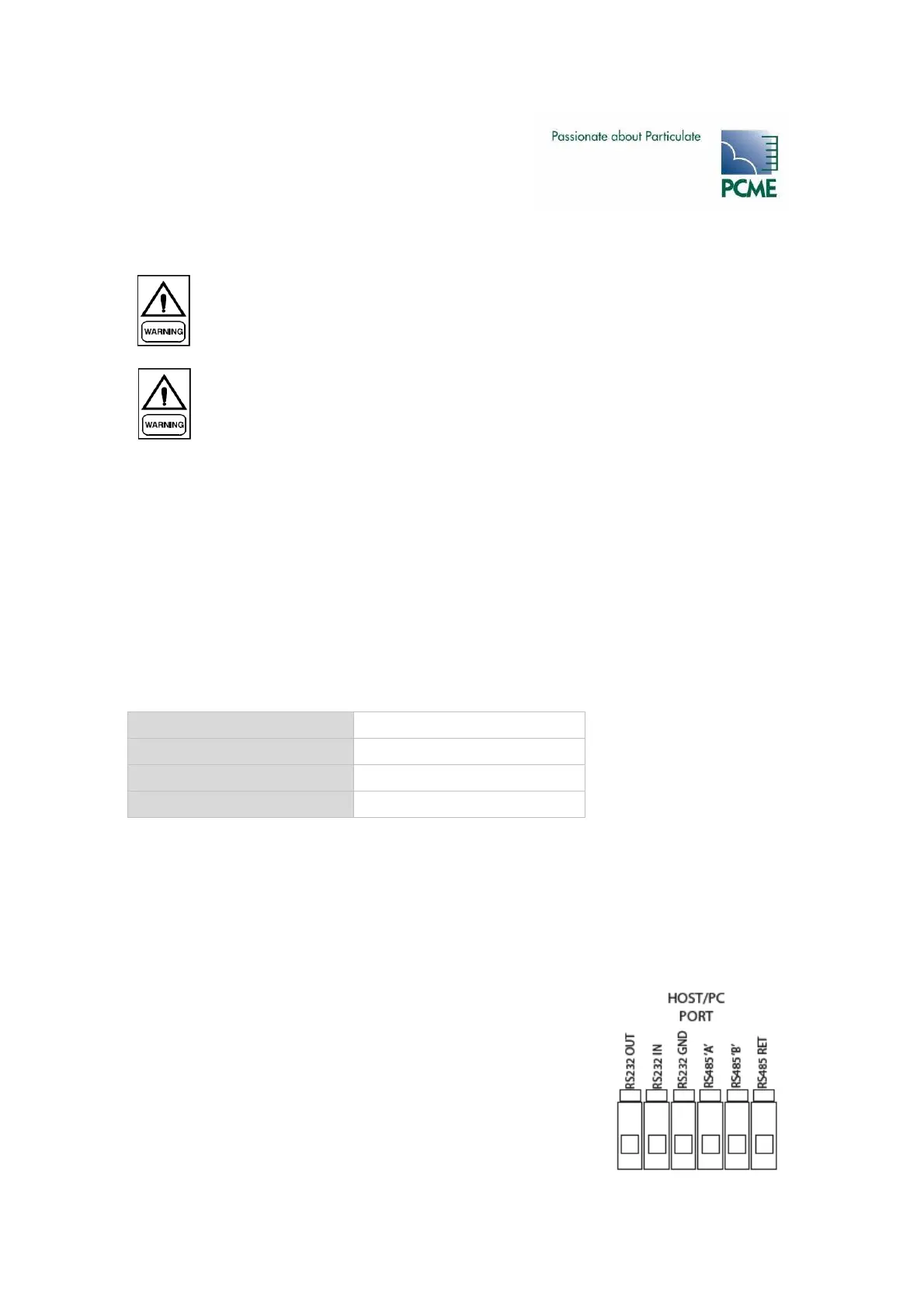
RS232/RS485 Connections
The Interface Module is fitted with an isolated RS232/485 port for connection to a PC/PLC.
Route a suitable cable through a vacant cable gland and connect as
shown to the HOST/PC PORT.
The maximum cable length for RS232 is 25 metres.
The maximum cable length for RS485 is 1000 metres.
0V Blue
Comms B Orange
Comms A Green
24V Brown