- PCME STACK 990 MANUAL: 25 -
Route the data cable for the other half of the network through the next cable gland and connect
to the Data Bus PL7 terminals.
Connect the cable screen from each cable to the nearest earth stud using an eyelet tag.
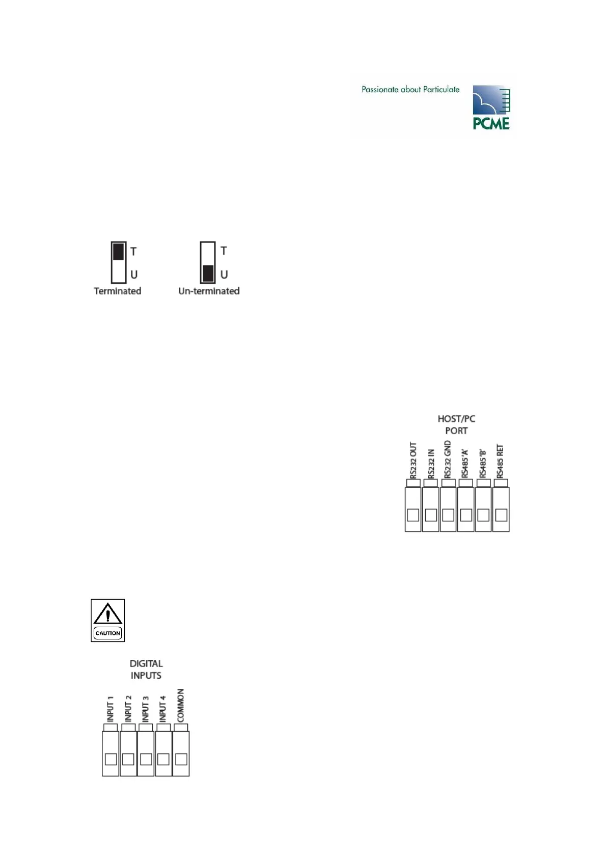
Bus Termination Switch (SW200)
The Bus Termination Switch (SW200) identifies the MultiController’s position in the network. Set
the switch to “U” (Un-terminated) if the unit is in the middle of the network. If the unit is at the
end of the network set the switch to “T” (Terminated).
RS232/RS485 Connections (PL2)
The MultiController is fitted with an isolated RS232/485 port for connection to a PC/PLC.
Route a suitable cable through a vacant cable gland and connect to
PL2 as shown.
The maximum cable length for RS232 is 25 metres.
The maximum cable length for RS485 is 1000 metres. RS485 can be
used to “daisy chain” several Multi-Controllers together with
separate Modbus addresses.
Digital Input Connections (PL3)
The MultiController has four digital (contact) inputs that may be assigned by the user.
These inputs are implemented using protected logic input gates. The inputs
should either be switched to ground by an external switch (e.g. a relay), or
driven from a low voltage logic output.
Route a suitable cable through a vacant cable gland and connect to
PL3 as shown. The connection should be made between the required
input and common ground.