- PCME STACK 990 MANUAL: 49 -
Testing Relay Ouput Modules
To test the correct operation of the ROMs select the QA menu.
To access the QA menu:
Select ‘Quality Assurance / ’Self Tests’ display
Select Device: Output Relay.
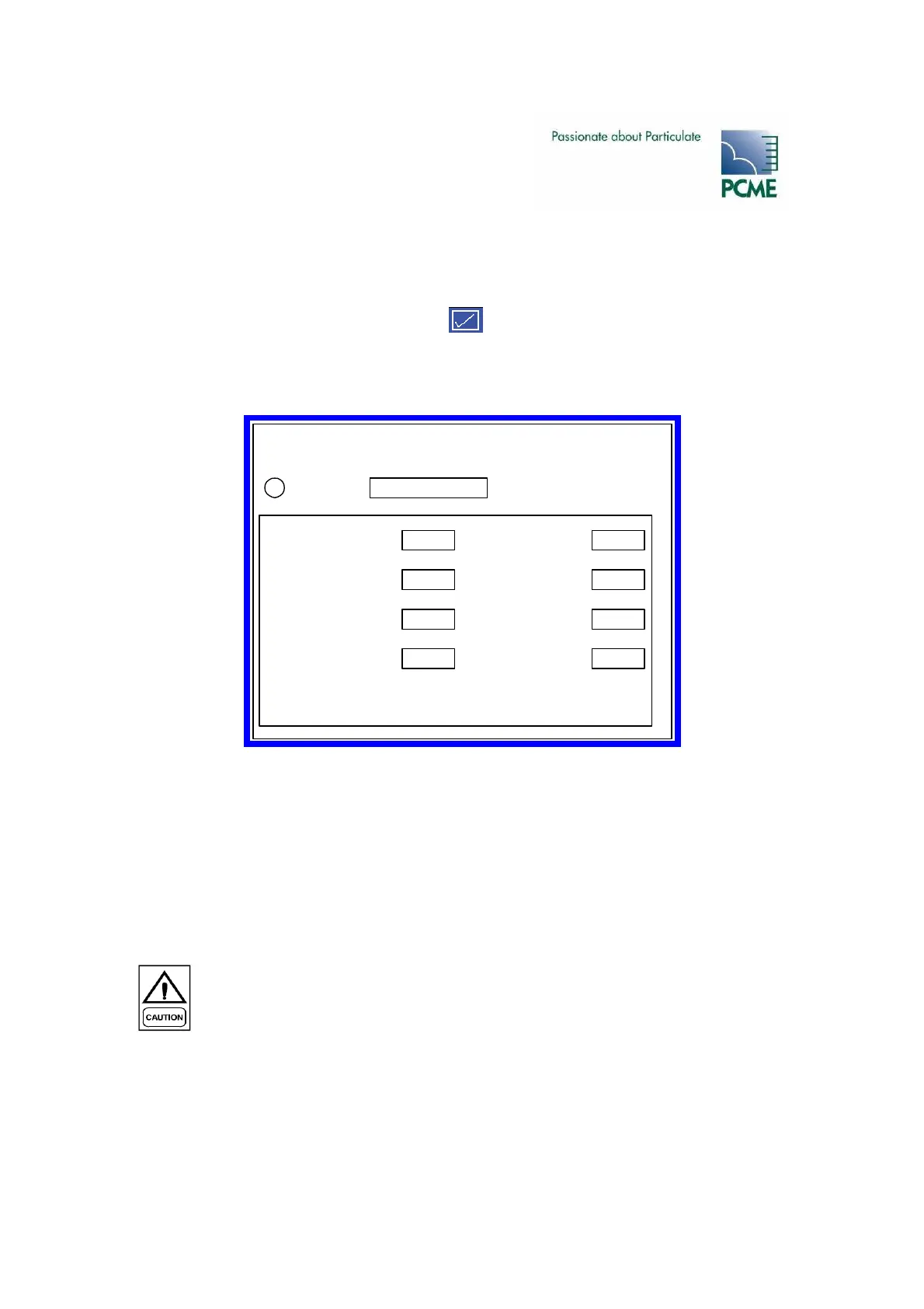
The following screen will be displayed:
The Comms Check tests the communication with the ROM.
The screen displays the current state of each relay. The status of each relay can also be checked
by viewing the LEDs on the ROM.
Relays can be temporarily selected ON by selecting the test button next to the relay to be tested.
Keep the button pressed to sustain the test.
Local 990 Sensor Relay Output
DO NOT switch mains voltage! The PCB tracks and connector are NOT mains rated.
The 990 sensor relay output has the following specification
• volt-free DPCO relay
• current rating 1Amp per contact
• option to wire normally open or normally closed
• non fail-safe operation only
Quality Assurance / Self Tests
Output RelayDevice:i
Comms Check OK
Relay 1 OFF
Test
Relay 5 OFF
Test
Relay 2 ON
Test
Relay 6 OFF
Test
Relay 3 OFF
Test
Relay 7 OFF
Test
Relay 4 OFF
Test
Relay 8 OFF
Test