EasyManuals Logo

PCME STACK 990 User Manual

PCME STACK 990
79 pages
To Next Page IconTo Next Page
To Previous Page IconTo Previous Page
Page #30 background imageLoading...
Page #30 background image
- PCME STACK 990 MANUAL: 30 -
5.4 Component Location
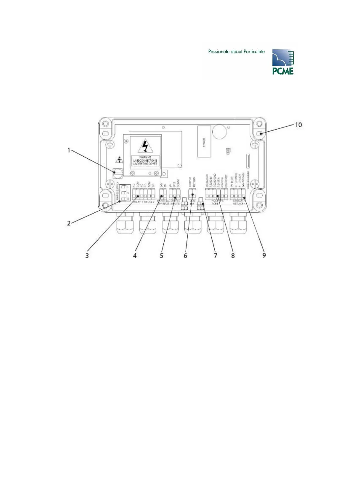
Figure 4-1 Interface Module Connections
1 Mains fuse (1Amp) 7 Earth stud - cable screen (2 off)
2 Mains supply terminals 8 RS232/RS485 terminals
3 Alarm contacts terminals 9 Data Bus (Sensor/Network Connector)
4 24V input 10 Fixing hole (4 off)
5 Digital inputs terminals
6 Isolated 4-20mA Output

Table of Contents

Questions and Answers:

Question and Answer IconNeed help?

Do you have a question about the PCME STACK 990 and is the answer not in the manual?

PCME STACK 990 Specifications

General IconGeneral
BrandPCME
ModelSTACK 990
CategoryMeasuring Instruments
LanguageEnglish

Related product manuals