Do you have a question about the PCME STACK 990 and is the answer not in the manual?
Details information for correct installation and commissioning of the instrument.
PCME Ltd. liability for injury or damage due to incorrect use of the manual.
Conformance to EU directives and harmonised standards for safety.
Hazards associated with process particulate and required precautions.
Operating conditions for optimum performance and safe equipment operation.
Glossary of abbreviations used throughout the manual.
List of related reference manuals and installation notes.
Details certification range, drift, measurement capability, and application constraints.
Technical specifications for the sensor, including temperature ratings, material, and weight.
Various sensor types, rod lengths, and ATEX/IECEx category options available.
Lists optional accessories like air purge fittings and stack connection options.
Specifications for Standard and PLUS systems, including menus, diagnostics, and outputs.
Describes optional modules like AIM, AOM, ROM, and their functionalities.
Safety warnings including process hazards, probe damage, and supply voltage.
Details the specification for PCME's data cabling, including pairs, shielding, and colour coding.
Recommendations for sensor location, grounding, and network layout for optimal performance.
Step-by-step guide on how to physically mount the sensor probe into the stack.
Instructions for wiring the sensor to the control unit via daisy-chained or spur-linked systems.
Configuration of bus termination, address, and communication settings using DIP switches.
Critical safety warnings related to hazardous voltages, earthing, and proper unit usage.
Lists necessary tools and materials, including drilling templates and cabling specifications.
Guidelines for selecting an appropriate mounting location for the MultiController.
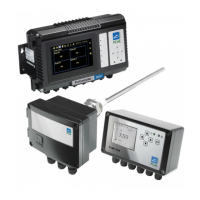
Identifies key components on the MultiController front panel.
Steps for mounting the control unit and making data and power connections.
Crucial safety warnings for hazardous voltages, earthing, and proper installation practices.
Outlines required tools, materials, and cabling specifications for the Interface Module.
Considerations for selecting an optimal mounting location for the Interface Module.
Details the location of various components within the Interface Module.
Procedures for mounting the module and connecting data and communication cables.
Overview of initial setup procedures applicable to both Standard and PLUS systems.
Steps for powering on the control unit and checking the display and icon bar.
Verifying communication setup and performing a master reset.
Process for automatically detecting and adding sensors to the multicontroller.
Adjusting fundamental settings for detected sensors, such as Time/Date and 4-20mA.
Explains the use of the calibration factor to scale readings to mg/m³.
Configuring warning and limit alarms, including instant and average alarm options.
Procedure for setting the system's time and date, with warnings about data loss.
Configuration of 4-20mA outputs, including scaling, filtering, and reassigning.
Assigning alarm types to relays and configuring their behavior for alarms.
Adjusting storage rates for long-term and short-term memory.
Accessing advanced sensor settings and managing devices (add/edit/delete).
Overview of the Controller QA screen functions for maintenance and testing.
Details on hardware self-checks for sensors, including zero, span, and contamination tests.
Procedures for placing sensors into maintenance mode for routine servicing.
How to clear active service messages by performing required maintenance actions.
Guidelines for inspecting and cleaning the sensor rod and enclosure.
Importance and method of calibrating sensors annually using isokinetic sampling.
Formula and example for calculating the calibration factor from test results.
Step-by-step process for obtaining a valid calibration factor and setting units.
How to use the controller's software calibration tool for simple calibration or data export.
Methodical approach to diagnosing and resolving network communication problems.
Using controller features like AutoDetect and checking device settings for troubleshooting.
Using LEDs to identify wiring errors or incorrect bus termination when using spurs.
Verifying correct power application to the sensor via internal LED status.
Checking communication status between controller and sensor via red LED behavior.
Identifying and resolving issues caused by voltage drop along long cables.
Diagnosing and fixing issues where sensor readings are not updating.
Troubleshooting unexpected readings by checking calibration, sensitivity, and grounding.
Visual representation of the primary displays available on the control unit.
Navigation flow for configuring basic sensor parameters.
Navigation flow for advanced sensor configuration and device management.
Navigation flow for system-wide settings like Time/Date and 4-20mA.
Overview of additional system functions accessible via menus.
Navigation flow for accessing Quality Assurance and Calibration screens.
| Enclosure Rating | IP65 |
|---|---|
| Application | Emissions monitoring for combustion and industrial processes |
| Operating Temperature | -20°C to +50°C |
| Output | 4-20 mA |
| Communication | Modbus TCP/IP |