- PCME STACK 990 MANUAL: 32 -
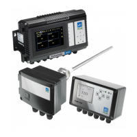
Digital Input Connections
The Interface Module has two digital (contact) inputs that may be assigned by the user.
These inputs are voltage-free and should
not be connected to logic outputs from
PLCs.
Route a suitable cable through a vacant cable gland and connect to
DIGITAL INPUTS as shown. The connection should be made between the
required input and common ground.
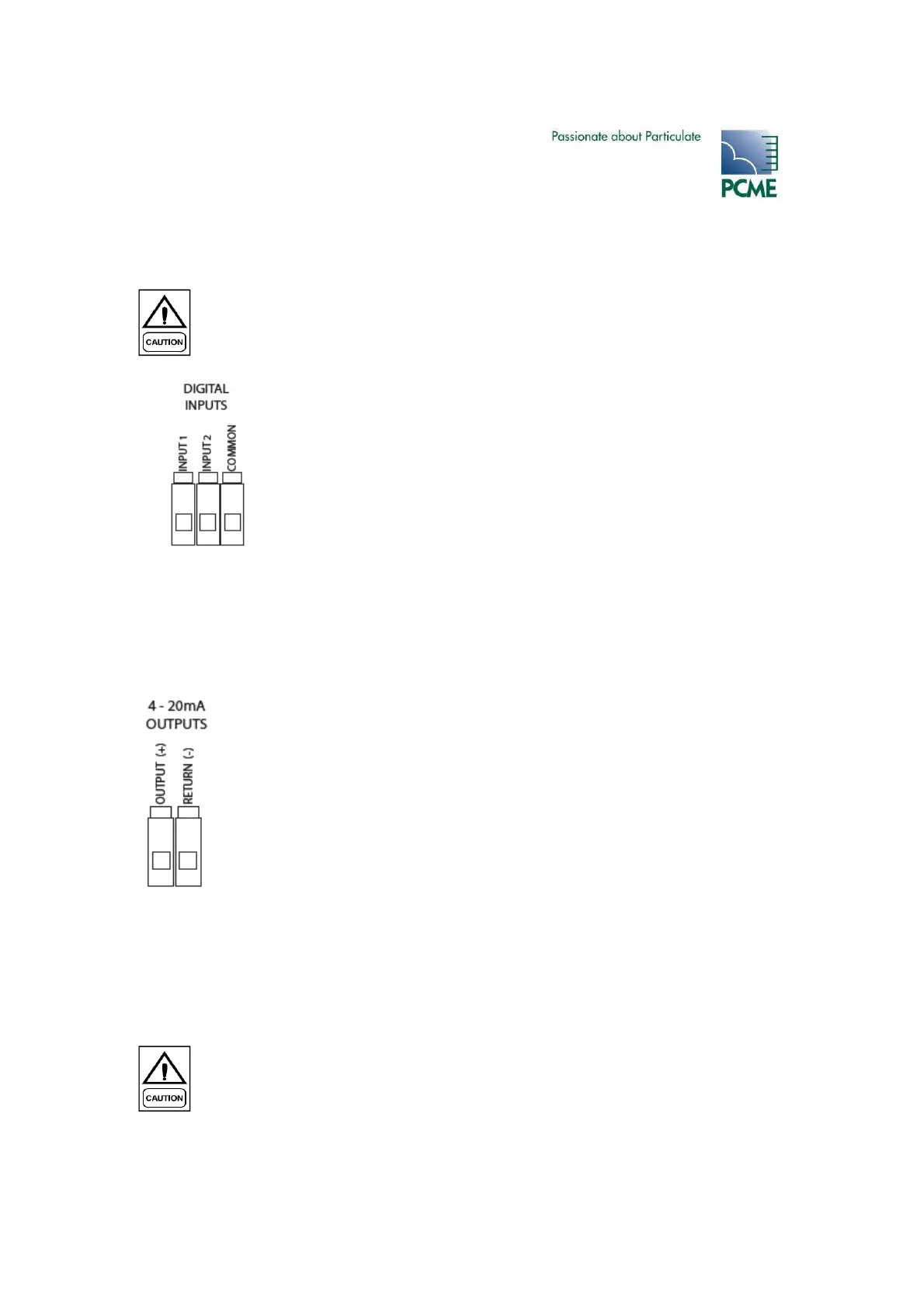
4-20mA Output Connections
The Interface Module is fitted with one isolated 4-20 mA outputs, each capable of driving a 250
Ohm load.
Route a suitable cable through a vacant cable gland and connect as shown.
Alarm Contact Connections
The Interface Module is fitted with two voltage-free SPCO with a 3A current rating. The relays
can be used to switch mains voltages.
The maximum current through the alarm
contacts must not exceed 3 Amps.