R
Ryan ThompsonAug 3, 2025
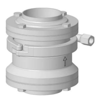
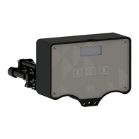
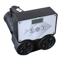
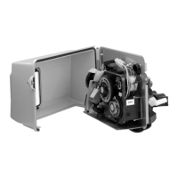
Why does my Pentair SUDMO IntelliTop 2.0 have no feedback signal?
- SSean PerryAug 3, 2025
If your Pentair Control Unit shows no feedback signal, it could be due to several reasons. First, the position measuring system (Teach-In) might not be appropriate for the spindle position; in this case, perform or repeat the Teach-In procedure. Second, the external initiators might be set incorrectly; adjust them according to their operating instructions. Third, there might be no or faulty associated feedback signals or external initiator; ensure the connections match the pin and plug configurations described in these operating instructions. Finally, the target might not be mounted on the process valve's spindle or the target could be faulty; check the target for correct mounting and condition.