98
Replacement of Components and Modules
Installation procedure:
→ Carefully insert the entire electronics module into the recess in the lower housing part.
→ Plug the electronics module carefully onto the contact pins for the position measuring system.
→ Refasten the electronics module with the Torx T10 screw (torque 0.4 Nm).
→ Reattach the electrical connections.
→ Check DIP switch positions (4-switch block for color coding, 8-switch block on DeviceNet electronics module
for address and Baud rate) and set the previously noted switch settings, if necessary.
→ If necessary, set AS interface address and jumper positions.
→ If required, make settings again, read out by PC software, using PC software.
→ Perform Teach-In procedure (see Chapter "16.1. Setting the position measuring system (Teach-In)").
Be sure to work carefully and cautiously, so that the electronics are not damaged.
→ Close the housing following the instructions in Chapter "8. Opening and Closing the Housing".
20.3. Changing the valves
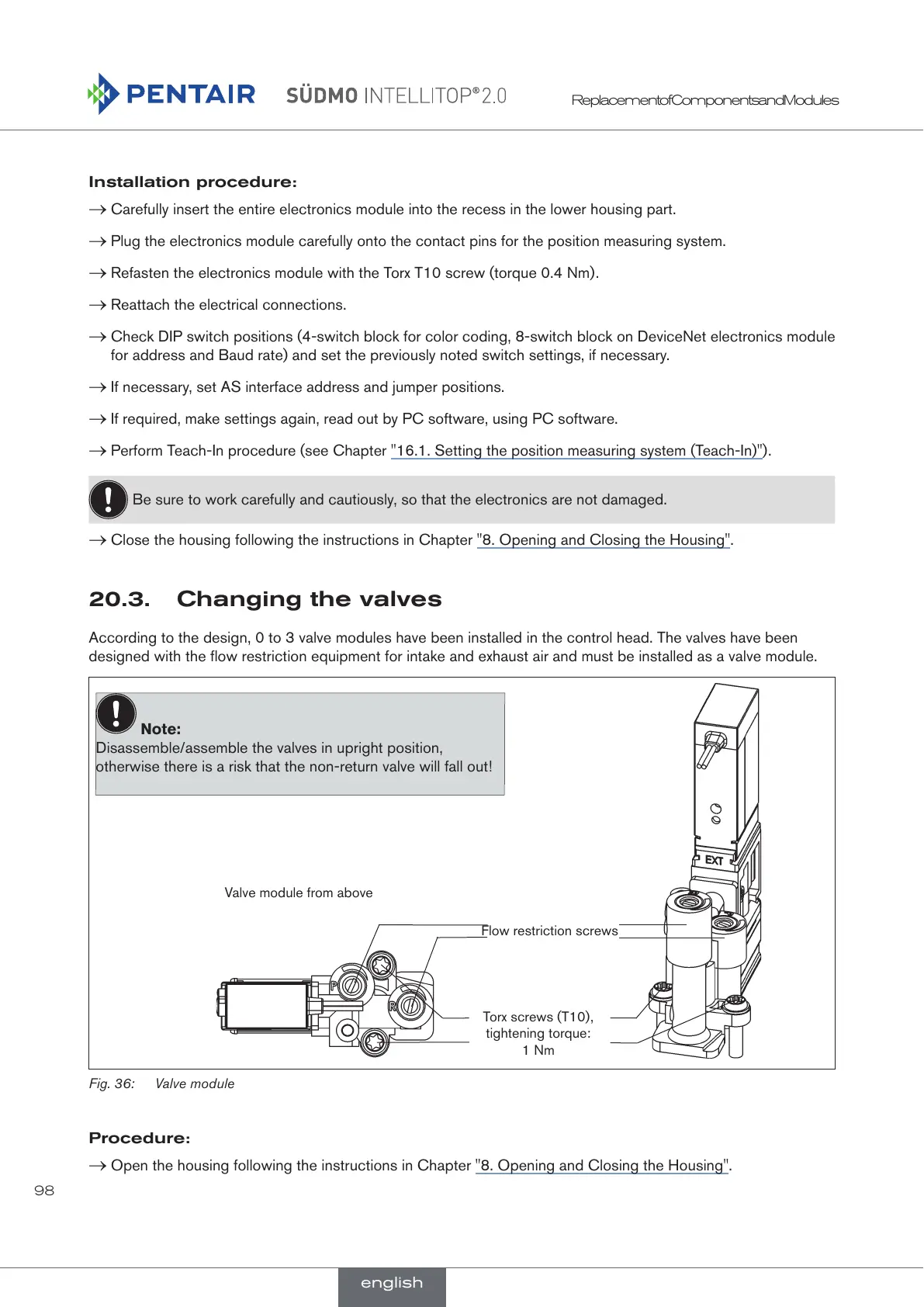
According to the design, 0 to 3 valve modules have been installed in the control head. The valves have been
designed with the flow restriction equipment for intake and exhaust air and must be installed as a valve module.
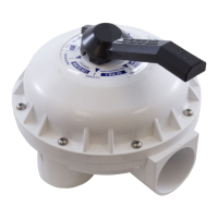
Valve module from above
Flow restriction screws
Torx screws (T10),
tightening torque:
1 Nm
Note:
Disassemble/assemble the valves in upright position,
otherwise there is a risk that the non-return valve will fall out!
Fig. 36: Valve module
Procedure:
→ Open the housing following the instructions in Chapter "8. Opening and Closing the Housing".
english
 Loading...