26
Technical Data
6.8. Factory settings in the firmware
The service interface may only be used in non-explosive atmosphere.
The control head is supplied with the following factory settings of the firmware:
6.8.1. Feedback fields (position measuring system)
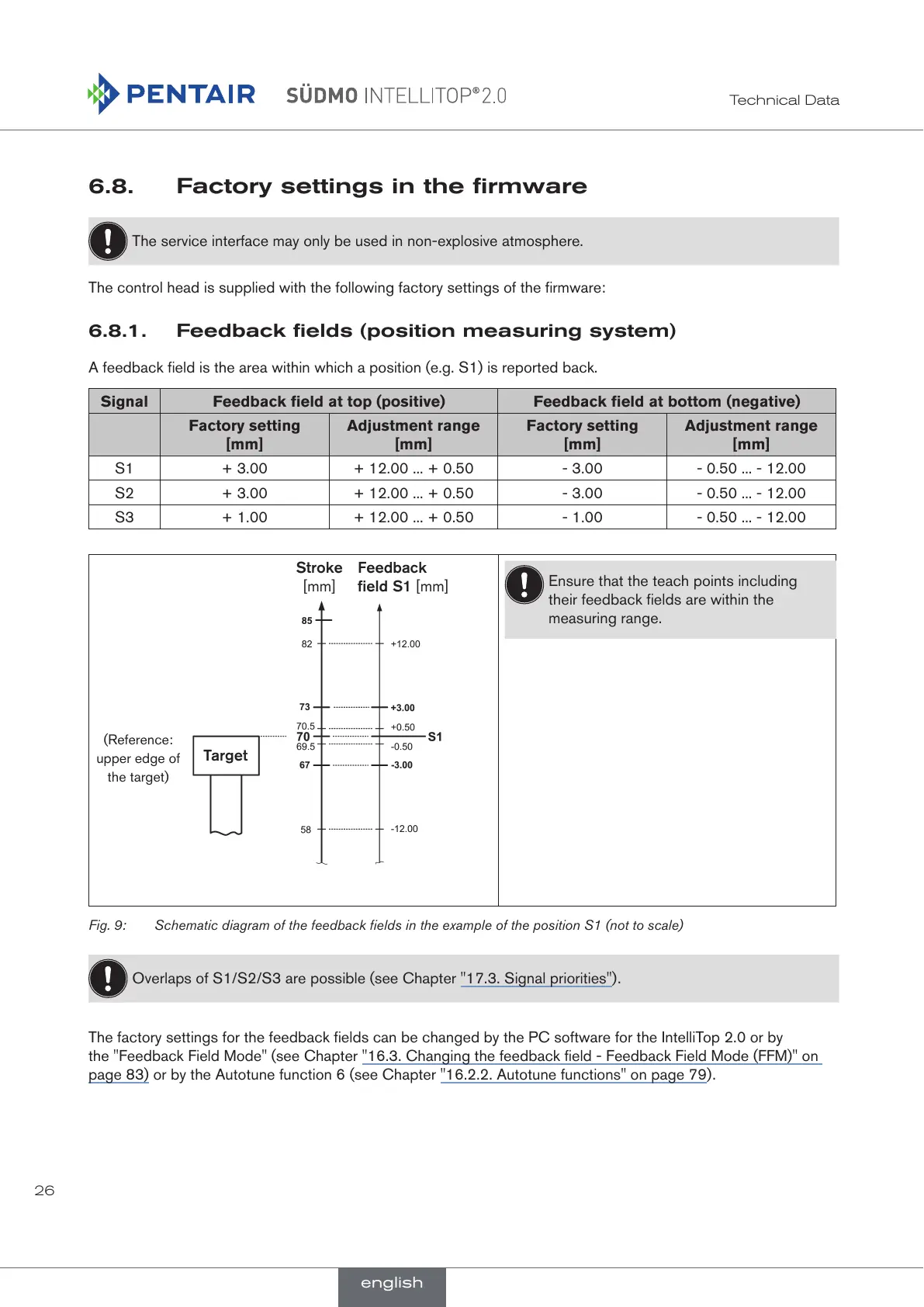
A feedback field is the area within which a position (e.g. S1) is reported back.
Signal Feedback field at top (positive) Feedback field at bottom (negative)
Factory setting
[mm]
Adjustment range
[mm]
Factory setting
[mm]
Adjustment range
[mm]
S1 + 3.00 + 12.00 ... + 0.50 - 3.00 - 0.50 ... - 12.00
S2 + 3.00 + 12.00 ... + 0.50 - 3.00 - 0.50 ... - 12.00
S3 + 1.00 + 12.00 ... + 0.50 - 1.00 - 0.50 ... - 12.00
Stroke
[mm]
Feedback
field S1 [mm]
Target
(Reference:
upper edge of
the target)
Ensure that the teach points including
their feedback fields are within the
measuring range.
Fig. 9: Schematic diagram of the feedback fields in the example of the position S1 (not to scale)
Overlaps of S1/S2/S3 are possible (see Chapter "17.3. Signal priorities").
The factory settings for the feedback fields can be changed by the PC software for the IntelliTop 2.0 or by
the "Feedback Field Mode" (see Chapter "16.3. Changing the feedback field - Feedback Field Mode (FFM)" on
page 83) or by the Autotune function 6 (see Chapter "16.2.2. Autotune functions" on page 79).
english
 Loading...