17
System Description
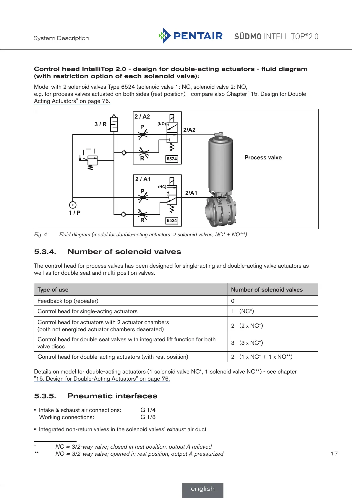
Control head IntelliTop 2.0 - design for double-acting actuators - fluid diagram
(with restriction option of each solenoid valve):
Model with 2 solenoid valves Type 6524 (solenoid valve 1: NC, solenoid valve 2: NO,
e.g. for process valves actuated on both sides (rest position) - compare also Chapter "15. Design for Double-
Acting Actuators" on page 76.
Process valve
Fig. 4: Fluid diagram (model for double-acting actuators: 2 solenoid valves, NC* + NO**
1
)
5.3.4. Number of solenoid valves
The control head for process valves has been designed for single-acting and double-acting valve actuators as
well as for double seat and multi-position valves.
Type of use Number of solenoid valves
Feedback top (repeater) 0
Control head for single-acting actuators 1 (NC*)
Control head for actuators with 2 actuator chambers
(both not energized actuator chambers deaerated)
2 (2 x NC*)
Control head for double seat valves with integrated lift function for both
valve discs
3 (3 x NC*)
Control head for double-acting actuators (with rest position) 2 (1 x NC* + 1 x NO**)
Details on model for double-acting actuators (1 solenoid valve NC*, 1 solenoid valve NO**) - see chapter
"15. Design for Double-Acting Actuators" on page 76.
5.3.5. Pneumatic interfaces
• Intake & exhaust air connections: G 1/4
Working connections: G 1/8
• Integrated non-return valves in the solenoid valves' exhaust air duct
* NC = 3/2-way valve; closed in rest position, output A relieved
** NO = 3/2-way valve; opened in rest position, output A pressurized
english
 Loading...