45
24 V DC - Design
10.5.2. Multi-pole connection
Internal cabling work is not required for models with multi-pole connection, which makes installation and start-up
on site considerably easier and quicker, reducing the risk of leaks. However, you will require the correspondingly
assembled cable sets with the following pin assignment:
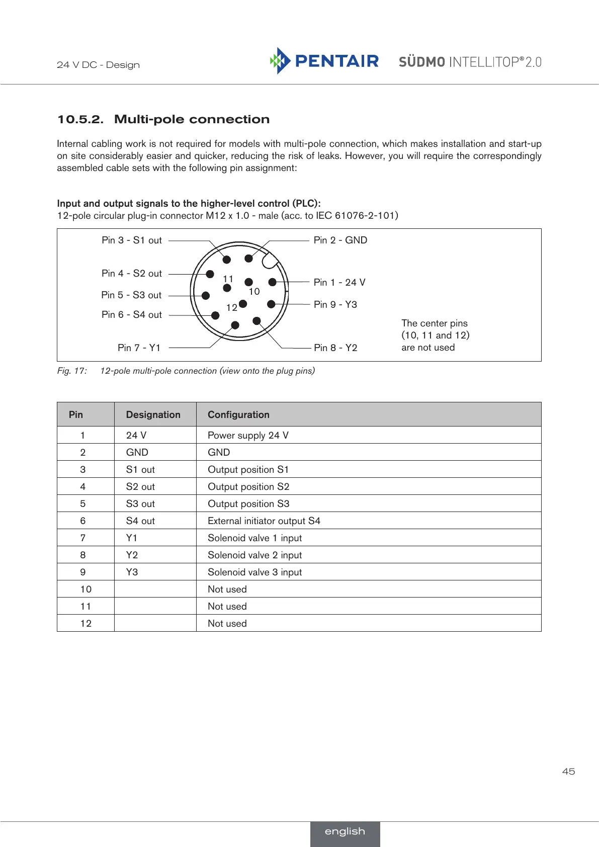
Input and output signals to the higher-level control (PLC):
12-pole circular plug-in connector M12 x 1.0 - male (acc. to IEC 61076-2-101)
10
Pin 9 - Y3
Pin 8 - Y2
12
Pin 6 - S4 out
Pin 7 - Y1
Pin 1 - 24 V
Pin 5 - S3 out
Pin 4 - S2 out
11
Pin 3 - S1 out Pin 2 - GND
The center pins
(10, 11 and 12)
are not used
Fig. 17: 12-pole multi-pole connection (view onto the plug pins)
Pin Designation Configuration
1 24 V Power supply 24 V
2 GND GND
3 S1 out Output position S1
4 S2 out Output position S2
5 S3 out Output position S3
6 S4 out External initiator output S4
7 Y1 Solenoid valve 1 input
8 Y2 Solenoid valve 2 input
9 Y3 Solenoid valve 3 input
10 Not used
11 Not used
12 Not used
english
 Loading...