55
DeviceNet Design
12. DEVICENET DESIGN
12.1. Definition
• The DeviceNet is a field bus system which is based on the CAN protocol (Controller Area Network). It enables
actuators and sensors (slaves) to be networked with higher-level controllers (master).
• The control head in the DeviceNet is a slave device according to the Predefined Master/Slave Connection Set
stipulated in the DeviceNet specification. Polled I/O, Bit Strobed I/O and Change of State (COS) are supported
as I/O connection variants.
• With DeviceNet it is necessary to differentiate between cyclical or event-driven high-priority process messages
(I/O Messages) and acyclical low-priority management messages (Explicit Messages).
• The protocol process conforms to the DeviceNet specification Release April 2010.
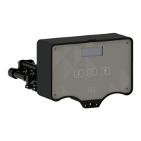
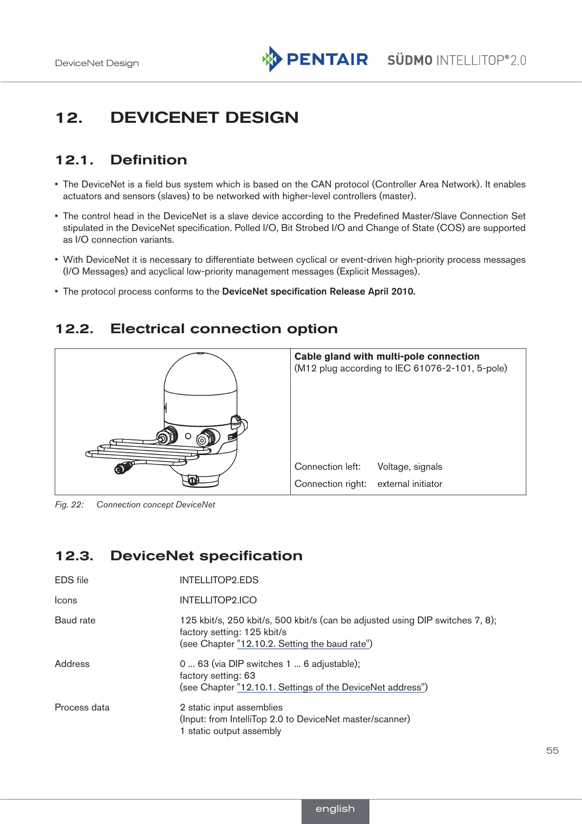
12.2. Electrical connection option
Cable gland with multi-pole connection
(M12 plug according to IEC 61076-2-101, 5-pole)
Connection left: Voltage, signals
Connection right: external initiator
Fig. 22: Connection concept DeviceNet
12.3. DeviceNet specification
EDS file INTELLITOP2.EDS
Icons INTELLITOP2.ICO
Baud rate 125 kbit/s, 250 kbit/s, 500 kbit/s (can be adjusted using DIP switches 7, 8);
factory setting: 125 kbit/s
(see Chapter "12.10.2. Setting the baud rate")
Address 0 ... 63 (via DIP switches 1 ... 6 adjustable);
factory setting: 63
(see Chapter "12.10.1. Settings of the DeviceNet address")
Process data 2 static input assemblies
(Input: from IntelliTop 2.0 to DeviceNet master/scanner)
1 static output assembly
english
 Loading...