14
System Description
5.3. Functions / options / designs
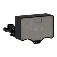
5.3.1. Structure of the control head
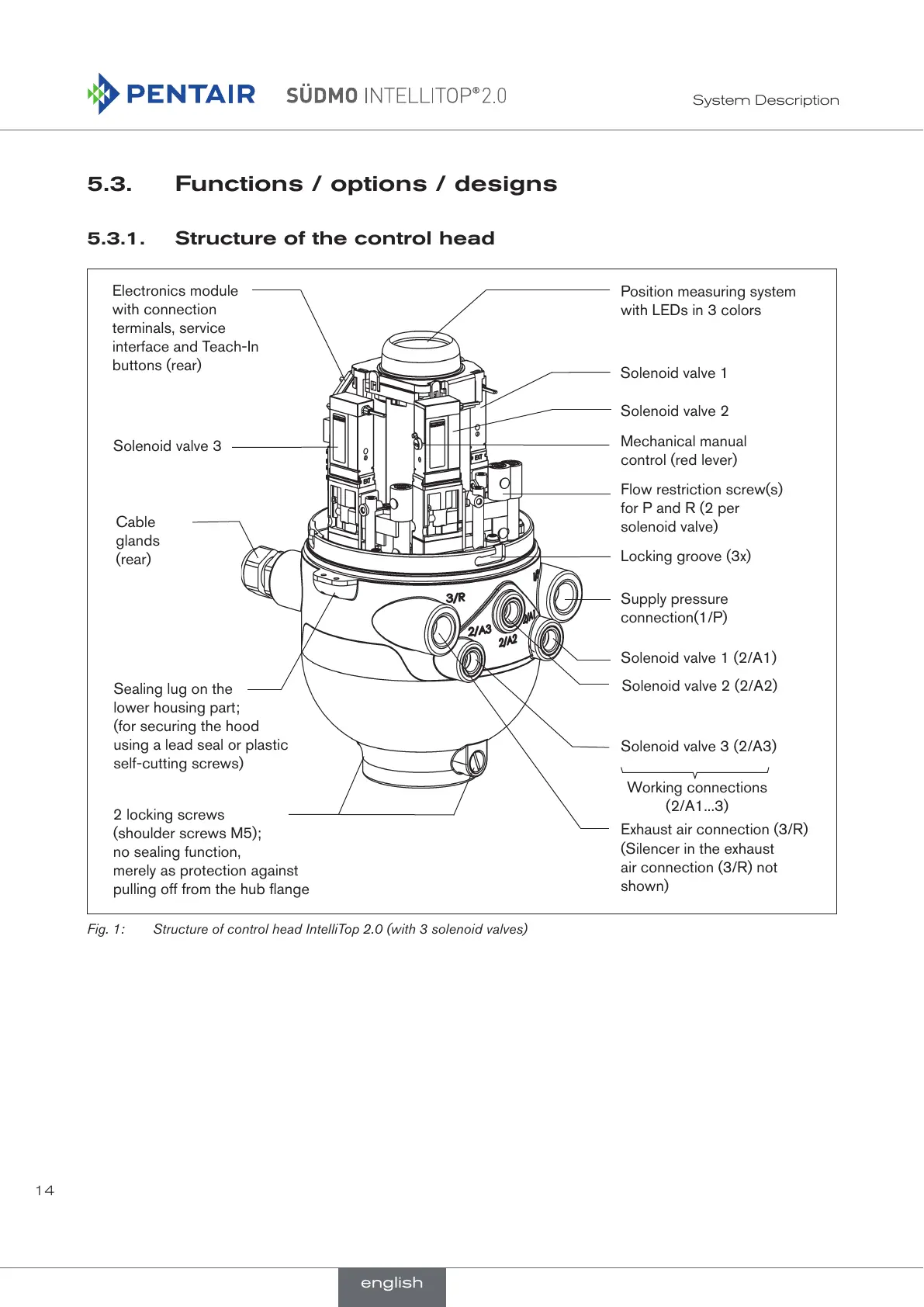
Electronics module
with connection
terminals, service
interface and Teach-In
buttons (rear)
Solenoid valve 3
Solenoid valve 2
Solenoid valve 1
Cable
glands
(rear)
Exhaust air connection (3/R)
Mechanical manual
control (red lever)
Supply pressure
connection(1/P)
Working connections
(2/A1...3)
Flow restriction screw(s)
for P and R (2 per
solenoid valve)
Solenoid valve 3 (2/A3)
Solenoid valve 2 (2/A2)
Solenoid valve 1 (2/A1)
Position measuring system
with LEDs in 3 colors
(Silencer in the exhaust
air connection (3/R) not
shown)
Sealing lug on the
lower housing part;
(for securing the hood
using a lead seal or plastic
self-cutting screws)
2 locking screws
(shoulder screws M5);
no sealing function,
merely as protection against
pulling off from the hub flange
Locking groove (3x)
Fig. 1: Structure of control head IntelliTop 2.0 (with 3 solenoid valves)
english
 Loading...