68
120 V AC Design
13. 120 V AC DESIGN
13.1. Electrical connection options
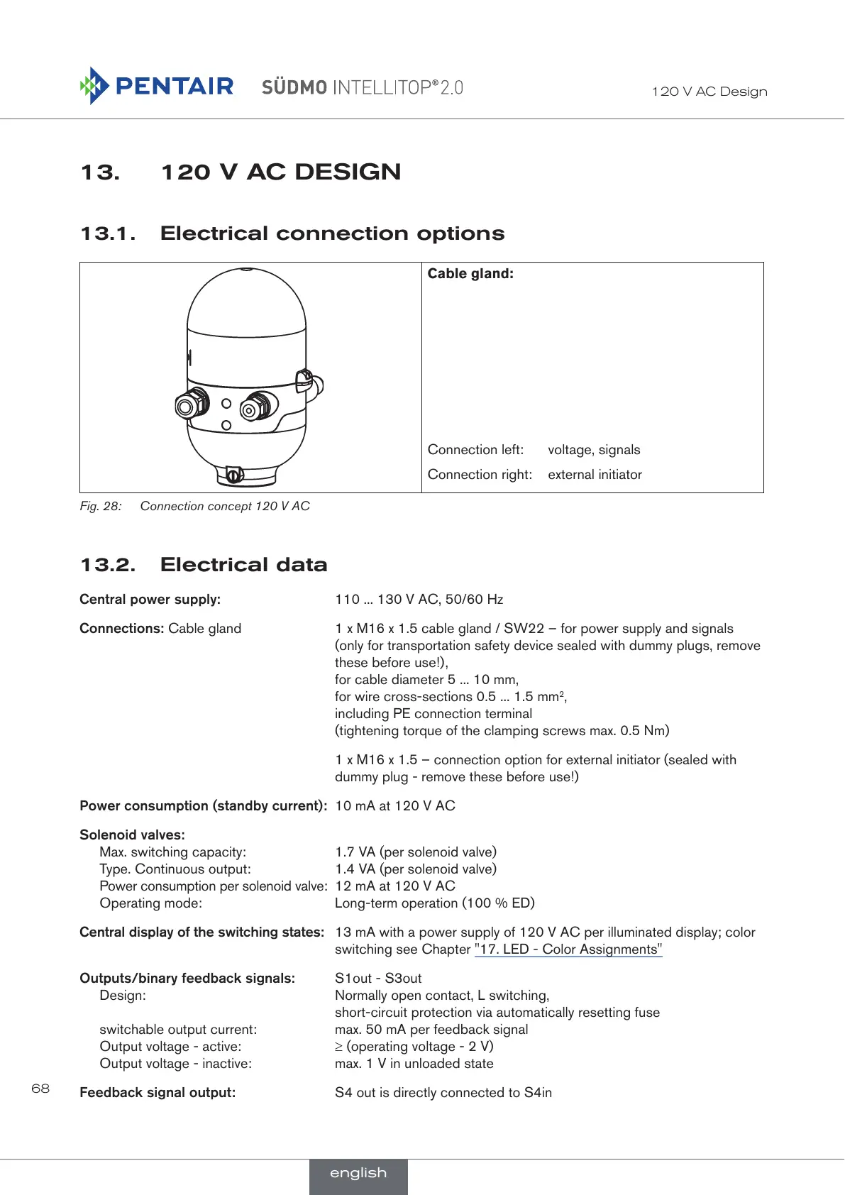
Cable gland:
Connection left: voltage, signals
Connection right: external initiator
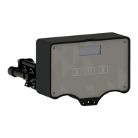
Fig. 28: Connection concept 120 V AC
13.2. Electrical data
Central power supply: 110 ... 130 V AC, 50/60 Hz
Connections: Cable gland 1 x M16 x 1.5 cable gland / SW22 – for power supply and signals
(only for transportation safety device sealed with dummy plugs, remove
these before use!),
for cable diameter 5 ... 10 mm,
for wire cross-sections 0.5 ... 1.5 mm
2
,
including PE connection terminal
(tightening torque of the clamping screws max. 0.5 Nm)
1 x M16 x 1.5 – connection option for external initiator (sealed with
dummy plug - remove these before use!)
Power consumption (standby current): 10 mA at 120 V AC
Solenoid valves:
Max. switching capacity: 1.7 VA (per solenoid valve)
Type. Continuous output: 1.4 VA (per solenoid valve)
Power consumption per solenoid valve: 12 mA at 120 V AC
Operating mode: Long-term operation (100 % ED)
Central display of the switching states: 13 mA with a power supply of 120 V AC per illuminated display; color
switching see Chapter "17. LED - Color Assignments"
Outputs/binary feedback signals: S1out - S3out
Design: Normally open contact, L switching,
short-circuit protection via automatically resetting fuse
switchable output current: max. 50 mA per feedback signal
Output voltage - active: ≥ (operating voltage - 2 V)
Output voltage - inactive: max. 1 V in unloaded state
Feedback signal output: S4 out is directly connected to S4in
english
 Loading...