41
24 V DC - Design
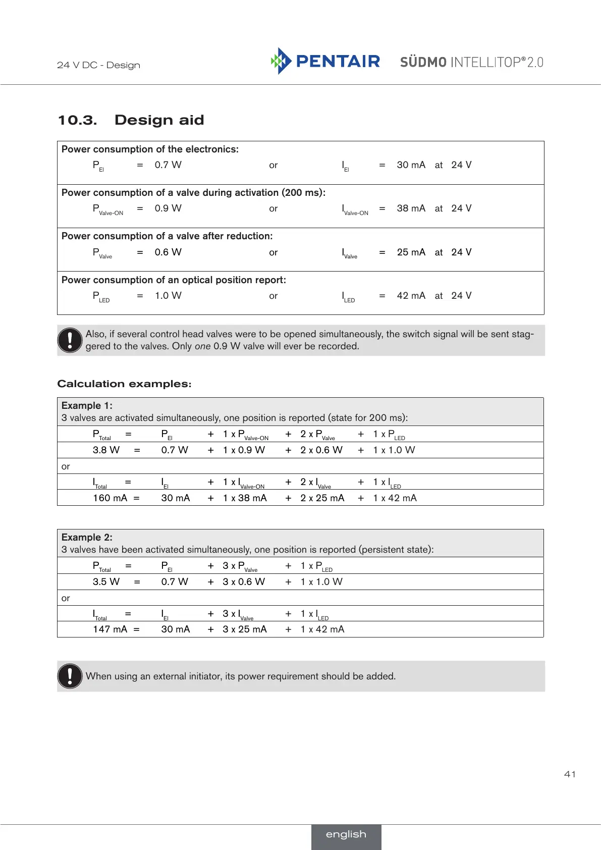
10.3. Design aid
Power consumption of the electronics:
P
El
= 0.7 W or I
El
= 30 mA at 24 V
Power consumption of a valve during activation (200 ms):
P
Valve-ON
= 0.9 W or I
Valve-ON
= 38 mA at 24 V
Power consumption of a valve after reduction:
P
Valve
= 0.6 W or I
Valve
= 25 mA at 24 V
Power consumption of an optical position report:
P
LED
= 1.0 W or I
LED
= 42 mA at 24 V
Also, if several control head valves were to be opened simultaneously, the switch signal will be sent stag-
gered to the valves. Only one 0.9 W valve will ever be recorded.
Calculation examples:
Example 1:
3 valves are activated simultaneously, one position is reported (state for 200 ms):
P
Total
= P
El
+ 1 x P
Valve-ON
+ 2 x P
Valve
+ 1 x P
LED
3.8 W = 0.7 W + 1 x 0.9 W + 2 x 0.6 W + 1 x 1.0 W
or
I
Total
= I
El
+ 1 x I
Valve-ON
+ 2 x I
Valve
+ 1 x I
LED
160 mA = 30 mA + 1 x 38 mA + 2 x 25 mA + 1 x 42 mA
Example 2:
3 valves have been activated simultaneously, one position is reported (persistent state):
P
Total
= P
El
+ 3 x P
Valve
+ 1 x P
LED
3.5 W = 0.7 W + 3 x 0.6 W + 1 x 1.0 W
or
I
Total
= I
El
+ 3 x I
Valve
+ 1 x I
LED
147 mA = 30 mA + 3 x 25 mA + 1 x 42 mA
When using an external initiator, its power requirement should be added.
english
 Loading...