53
AS Interface - Design
The optional ribbon cable terminal contacts the AS interface cable harness by means of penetration technology which
allows installation by "clipping in" the AS interface cable harness without cutting and without removing insulation.
Screws
M12 plug-in con-
nector branch circuit
Procedure:
→ Open the ribbon cable terminal
(loosen screws and remove cover)
→ Insert cable harness
→ Close ribbon cable terminal again
→ Tighten the screws
Loosen the thread-forming screws slightly and position
them on the existing threaded hole and screw in.
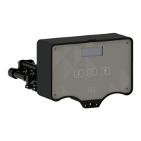
Fig. 21: Optional ribbon cable terminal for AS interface cable harness
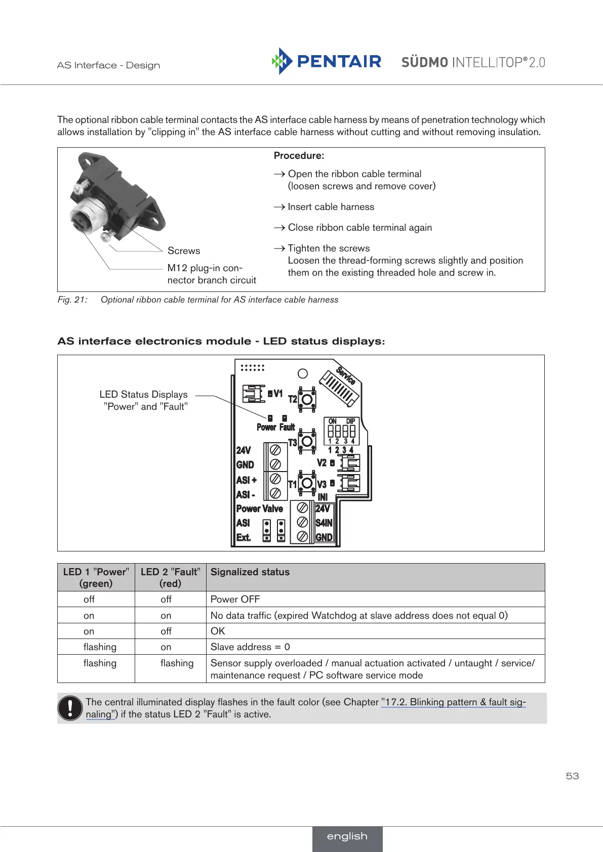
AS interface electronics module - LED status displays:
LED Status Displays
"Power" and "Fault"
LED 1 "Power"
(green)
LED 2 "Fault"
(red)
Signalized status
off off Power OFF
on on No data traffic (expired Watchdog at slave address does not equal 0)
on off OK
flashing on Slave address = 0
flashing flashing Sensor supply overloaded / manual actuation activated / untaught / service/
maintenance request / PC software service mode
The central illuminated display flashes in the fault color (see Chapter "17.2. Blinking pattern & fault sig-
naling") if the status LED 2 "Fault" is active.
english
 Loading...