EasyManuals Logo

Pentair SuperFlo VS Installation Guide

Pentair SuperFlo VS
148 pages
To Next Page IconTo Next Page
To Previous Page IconTo Previous Page
Page #113 background imageLoading...
Page #113 background image
113
Espagnol
El acceso a estos terminales se encuentra muy cerca de los conectores principales que transportan una
tensión capaz de causar lesiones personales o daños en los equipos al entrar en contacto con ellos.
Se debe desconectar la alimentación eléctrica al acceder a esta zona.
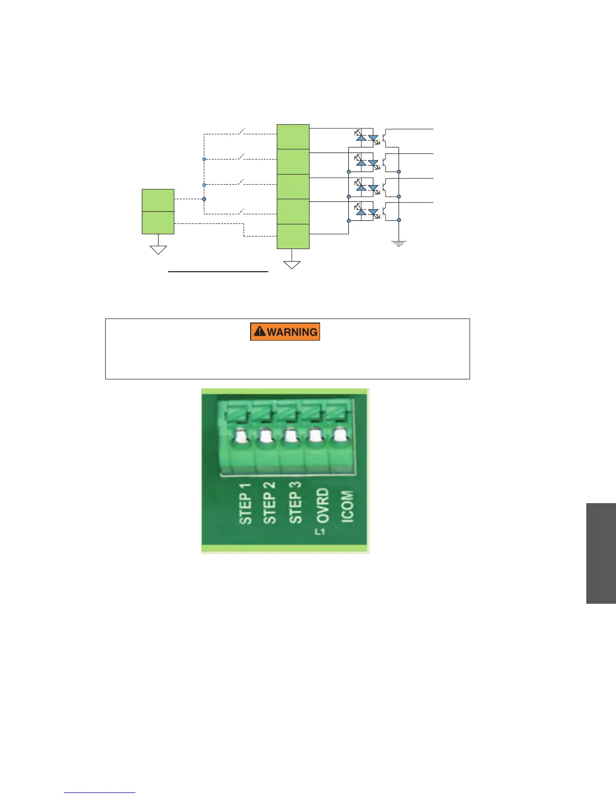
Figura 6: diagrama de cableado para las entradas del sistema de control de automatización
Rango de suministro externo:
18-30 V CA (24V CA+/- 20%)
9-30 V CC (12/24 V CC +/- 20%)
UI DIGITAL
INPUT CONNECTOR
J202
STEP 1
(pin 1)
STEP 2
(pin 2)
STEP 3
(pin 3)
OVER RIDE
(pin 4)
COMMON
(pin 5)
Vac or
VDC
GND
EXTERNAL SUPPLY
Automation System or
Solar System Controller
Programador de la bomba
Figura 7: conector de entrada del sistema de control de automatización

Table of Contents

Other manuals for Pentair SuperFlo VS

Questions and Answers:

Question and Answer IconNeed help?

Do you have a question about the Pentair SuperFlo VS and is the answer not in the manual?

Pentair SuperFlo VS Specifications

General IconGeneral
Horsepower1.5 HP
ControlDigital
Energy EfficiencyENERGY STAR Certified
Warranty1-year limited warranty
Motor TypePermanent Magnet Motor
Maximum Head50 feet
Speed RangeVariable Speed
TypeVariable Speed
Union Connection2-inch
Port Size2-inch

Related product manuals