18
Control with Automation Control System Inputs
The user can run the
SuperFlo
®
VS Variable Speed
Pump at the programmed STEP 1, STEP 2, STEP 3,
or OVERRIDE speeds by utilizing the four automation control system inputs. STEP 1, STEP 2, STEP 3, or
OVERRIDE are equivalent to input 1, 2, 3 or OVRD respectively.
Note: The controller is rated to accept inputs of 18V-30V AC (24V AC+/- 20%) and 9-30V DC (12/24V DC +/-
20%).
Note: The pump will detect either a 50/60Hz for AC input or an active high signal for DC inputs.
The items below describe the functionality of the inputs:
1. If the user provides any one of the four (4) inputs, then the corresponding ACTIVE STEP LED will blink
every one (1) second. The SPEED LED and corresponding bar graph LED will be illuminated to
indicate the input is functioning properly.
2. The START LED will be OFF when an input is present.
Note: A generic wiring diagram is provided in gure 6 (on page 17) for connecting the pump to an “Automation
System Controller”. This concept can be applied to a solar system or any other type of control system.
Note: There is no schedule for automation system inputs. The timing for each speed is controlled directly by the
inputs.
Note: The digital inputs have the highest priority amongst all inputs (i.e., keypad or digital). Therefore the User
Interface inputs will be ignored when a digital input is present.
Note: If more than one input (switch) is present, then the pump will give priority to the highest number input.
Therefore OVER
RIDE has highest priority followed by STEP 3, then STEP 2, then STEP 1.
Note: If no automation input is detected, the pump will automatically start the 24 hour schedule if the START key
was pressed prior to the application of an input.
Note: If using external devices it is the users responsibility to verify appropriate power and speed conditions.
Refer to proper external device manual.
Access to these terminals is in close proximity to the mains connectors which carr y line voltage
capable of causing personal injury or damaging the equipment if contact is made. Power should
be turned o when accessing this area.
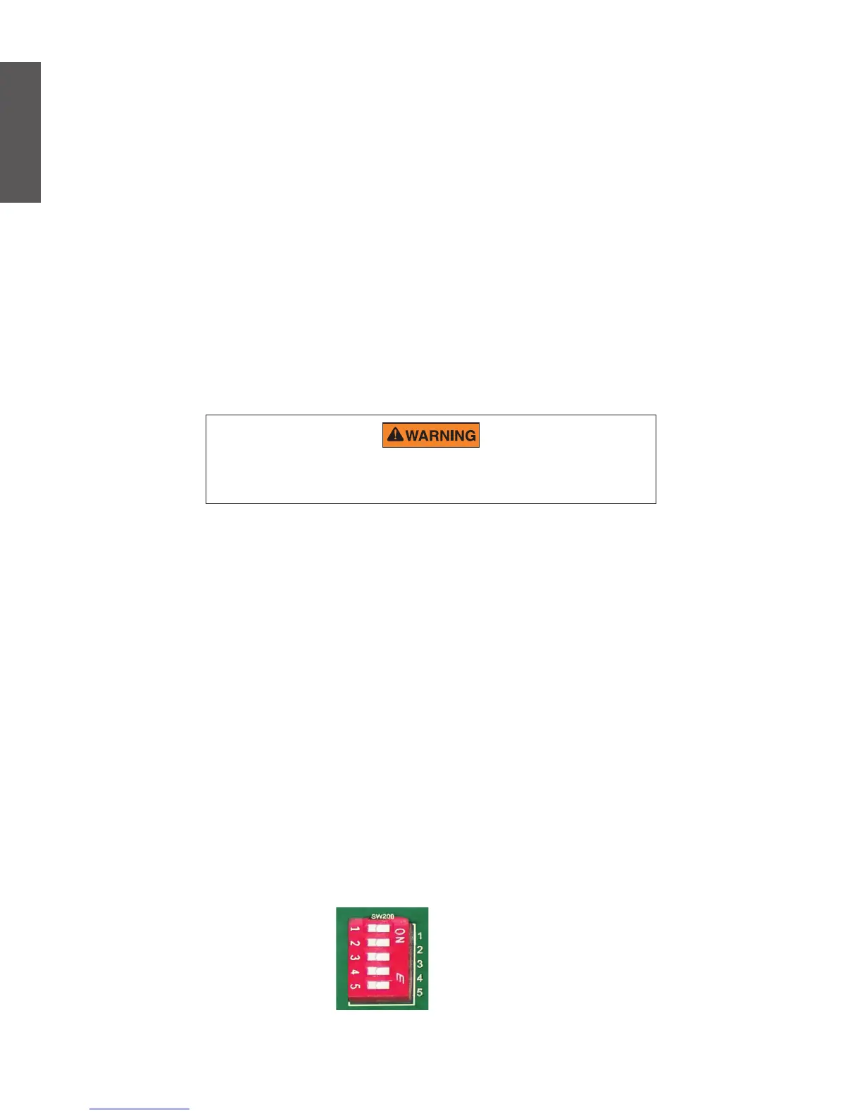
DIP Switches
Figure 8: DIP Switches
The DIP switches are used for factory programming.
English

 Loading...