EasyManuals Logo

Pentair SuperFlo VS Installation Guide

Pentair SuperFlo VS
148 pages
To Next Page IconTo Next Page
To Previous Page IconTo Previous Page
Page #137 background imageLoading...
Page #137 background image
137
L'accesso a questi terminali è molto vicino ai connettori alla rete elettrica, che sono attraversati da una tensione
in grado di provocare lesioni o danneggiare le apparecchiature in caso di contatto. L'alimentazione deve essere
interrotta quando si accede a quest'area.
Intervallo alimentazione esterna:
18-30 V AC (24 V AC +/- 20%)
9-30 V DC (12/24 V DC +/- 20%)
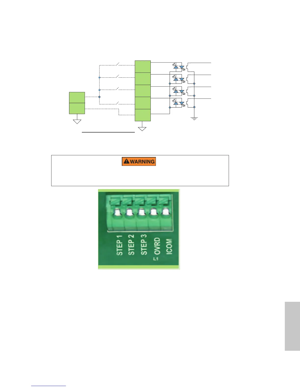
Figura 6: Diagramma del cablaggio per gli input dell'impianto di controllo di automazione
UI DIGITAL
INPUT CONNECTOR
J202
STEP 1
(pin 1)
STEP 2
(pin 2)
STEP 3
(pin 3)
OVER RIDE
(pin 4)
COMMON
(pin 5)
Vac or
VDC
GND
EXTERNAL SUPPLY
Automation System or
Solar System Controller
Controller della pompa
Figura 7: Connettore di input dell'impianto di controllo di automazione
Italiano

Table of Contents

Other manuals for Pentair SuperFlo VS

Questions and Answers:

Question and Answer IconNeed help?

Do you have a question about the Pentair SuperFlo VS and is the answer not in the manual?

Pentair SuperFlo VS Specifications

General IconGeneral
Horsepower1.5 HP
ControlDigital
Energy EfficiencyENERGY STAR Certified
Warranty1-year limited warranty
Motor TypePermanent Magnet Motor
Maximum Head50 feet
Speed RangeVariable Speed
TypeVariable Speed
Union Connection2-inch
Port Size2-inch

Related product manuals