Adjustment
13 - 43
2
1
4
Fig. 13 - 40
2
2
3
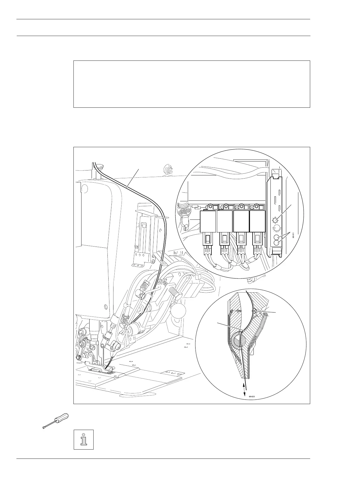
13.07.02 Setting the evaluation function of the photoelectric beam
Requirement
1. If the bridle tape 2 is in the detection range of the photoelectric beam 3 (regulate air jet
on, valve Y52 activated), none of the LEDs 4 should be on.
2. If the bridle tape 2 is outside the detection range of the photoelectric beam 3, both
LEDs 4 should be on.
● Adjust the trimmer 1 in accordance with the requirements.
To check the setting tighten and release bridle tape 2.
For further information see Data sheet for the evaluation of the photoelectric
beam.
 Loading...


