Adjustment
13 - 2
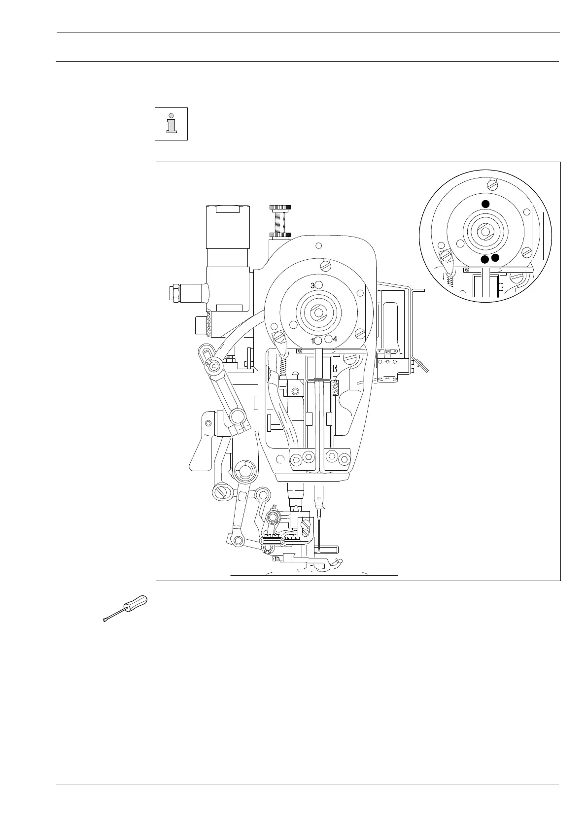
13.04 Checking and adjusting aids
By inserting the adjustment pin (ø 5 mm) into holes 1, 3 and 4 the needle bar
can be fixed precisely in the desired position.
● Turn the handwheel until the needle bar is approximately in the desired position.
● Insert the adjustment pin into the respective hole and apply pressure.
● Turn the handwheel slightly forwards and backwards until the adjustment pin engages in
the rear crank recess and thus blocks the machine.
Hole 1 = top dead center of the needle bar (TDC)
Hole 3 = bottom dead center of the needle bar (BDC)
Hole 4 = 0.8 mm below the top dead center of the needle bar (0.8 below TDC)
Fig. 13 - 01